Blog :

Nozzle Heater Packed

Nozzle Heater Packed

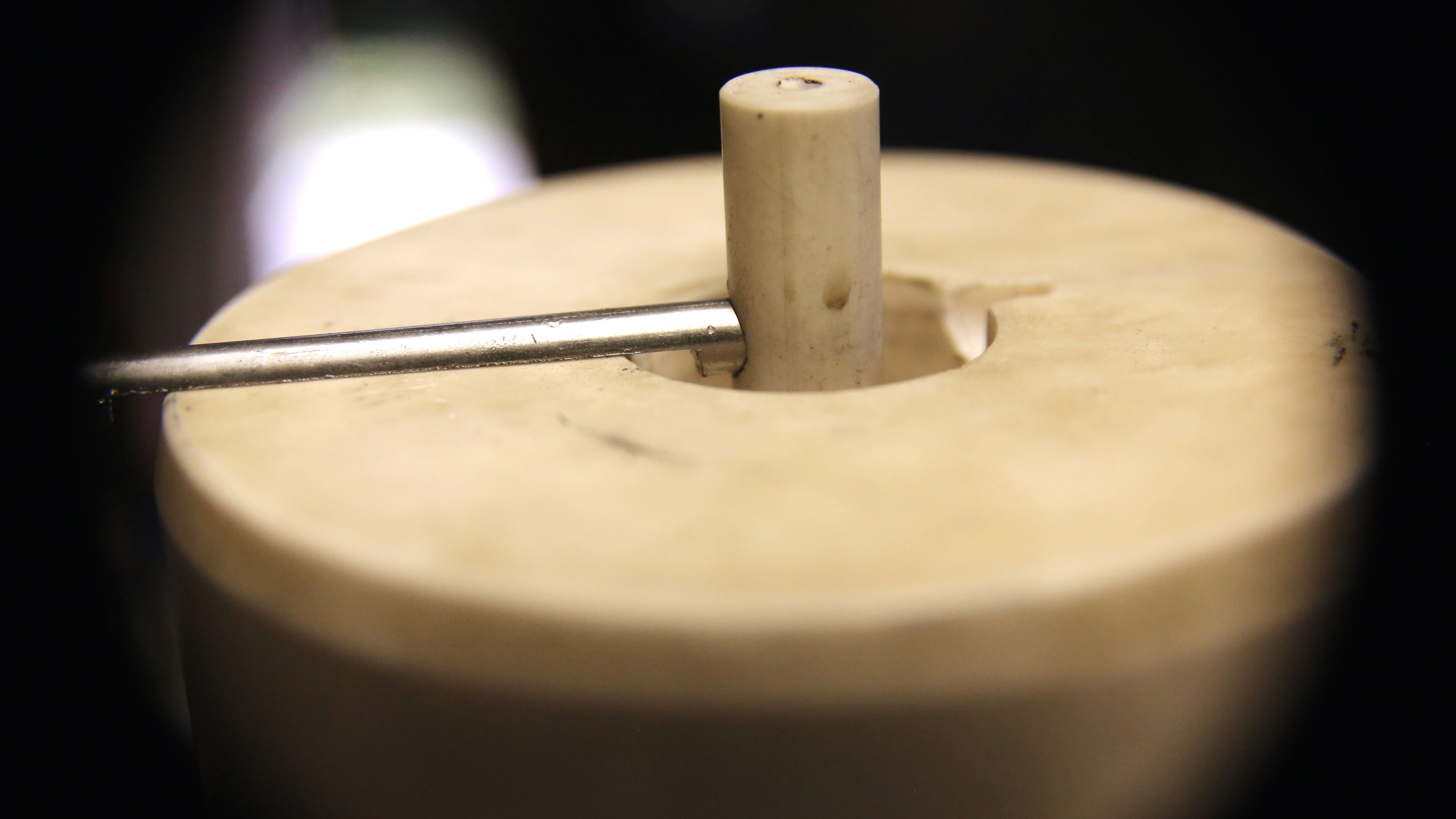
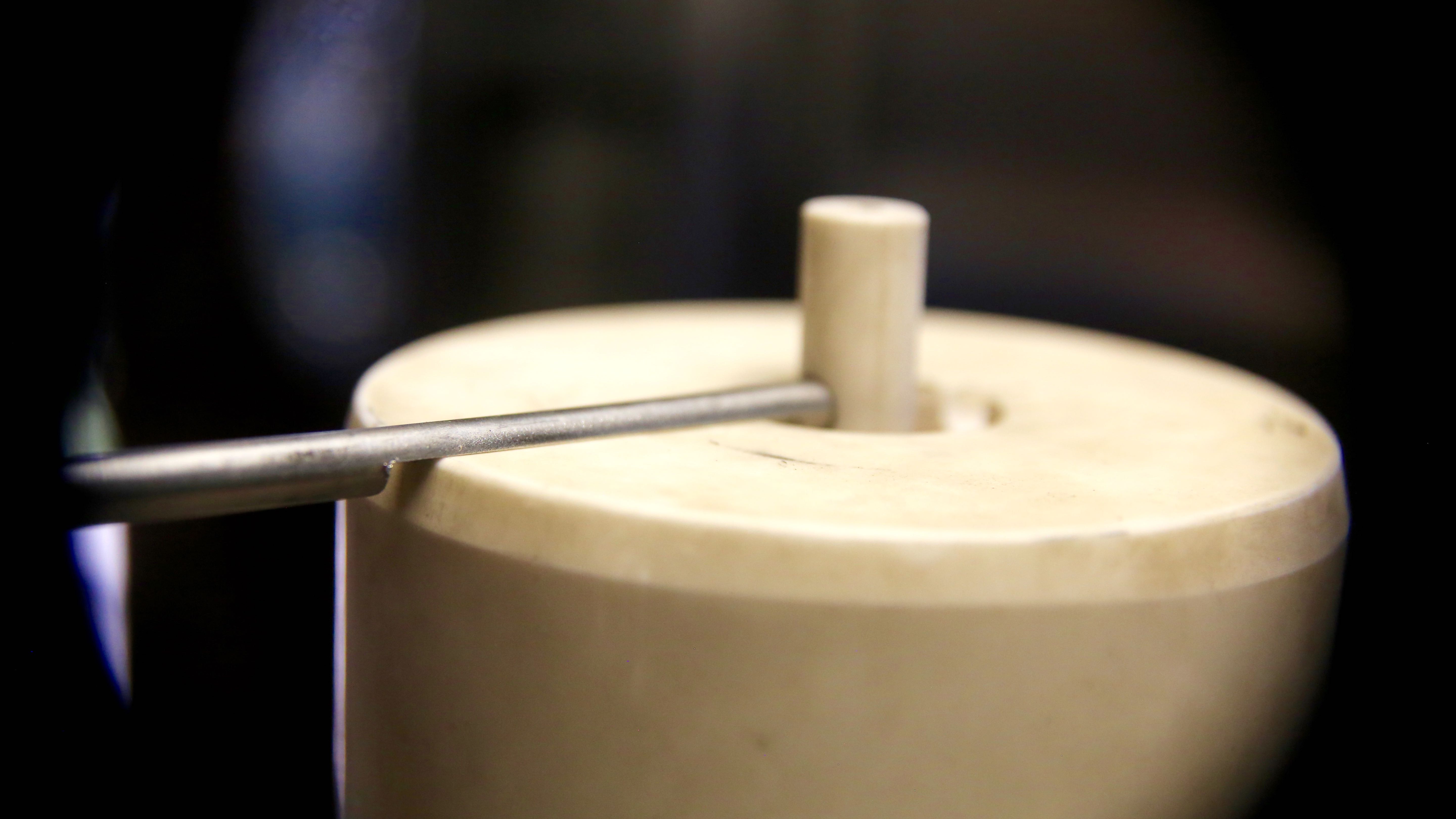
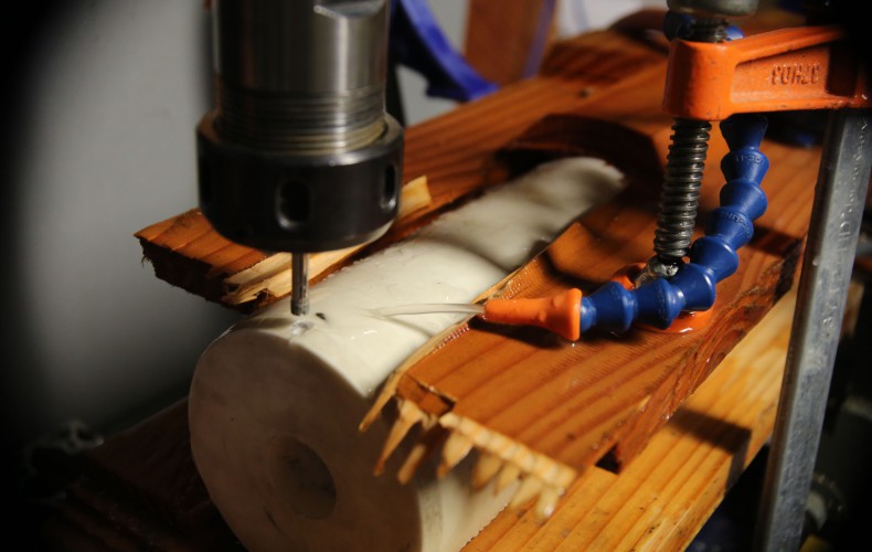
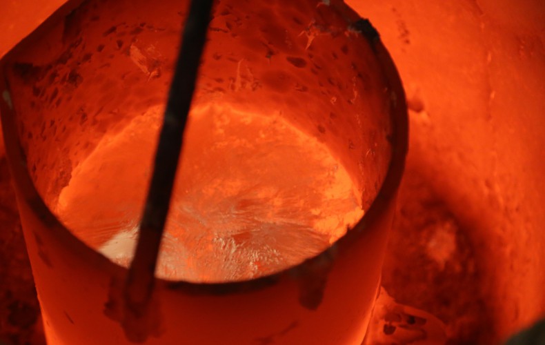
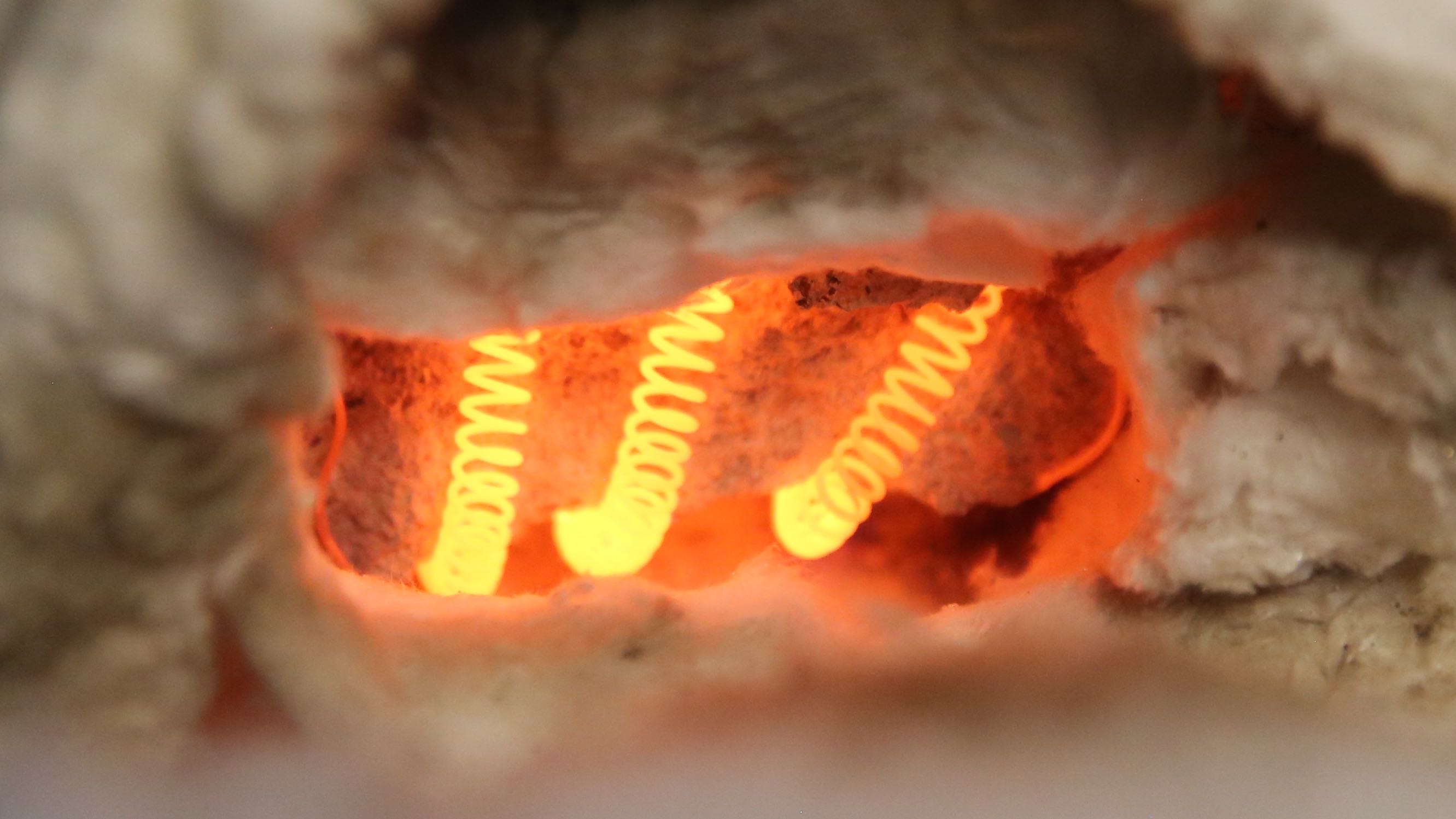
Our first nozzle heater coil attempt failed miserably. The refractory selected for the task was far too course and we were unable to fill the nozzle cavity properly. So when it heated up, the heater coil sagged and shorted out. But – we did learn from our mistake(s)!

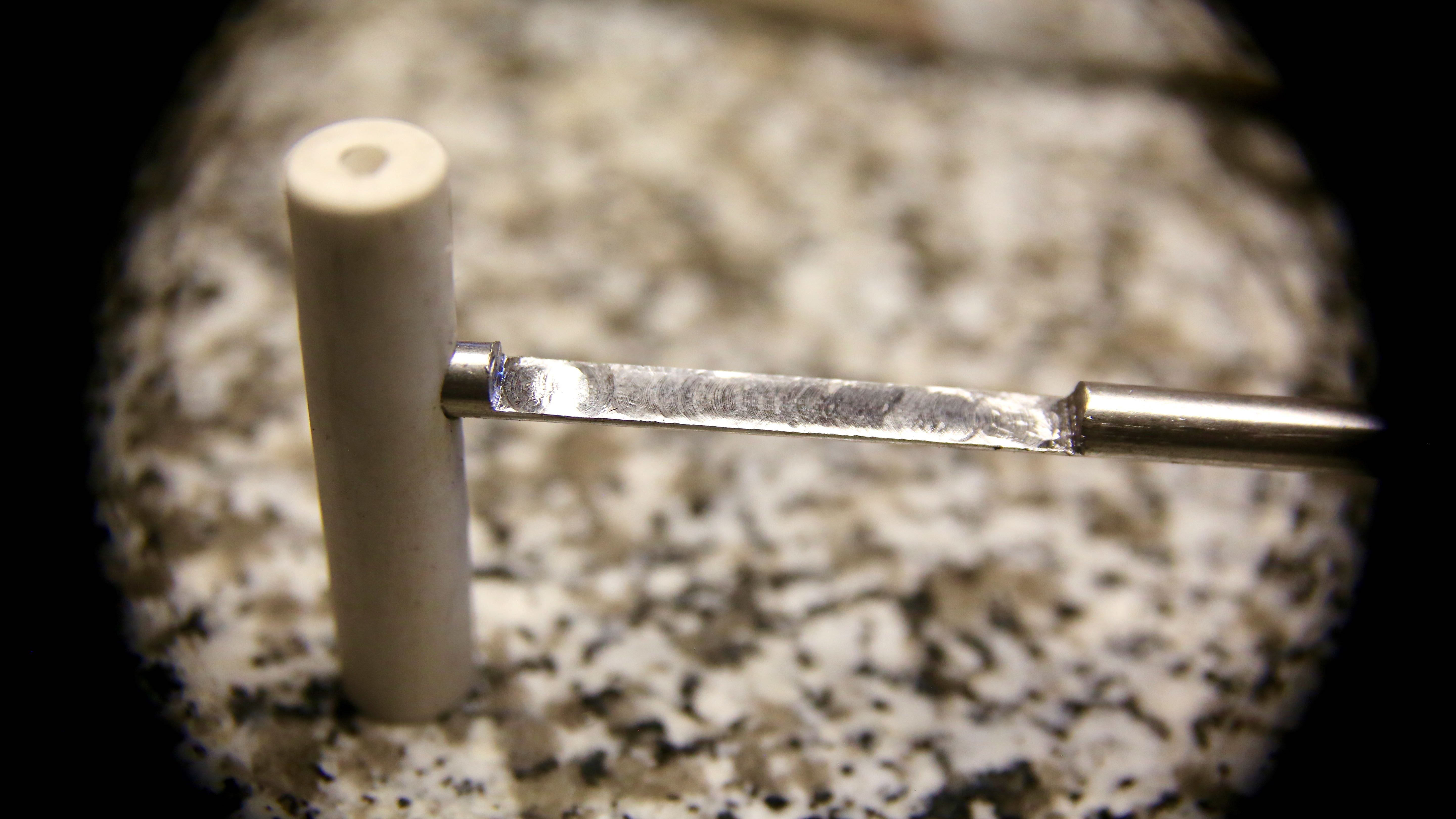
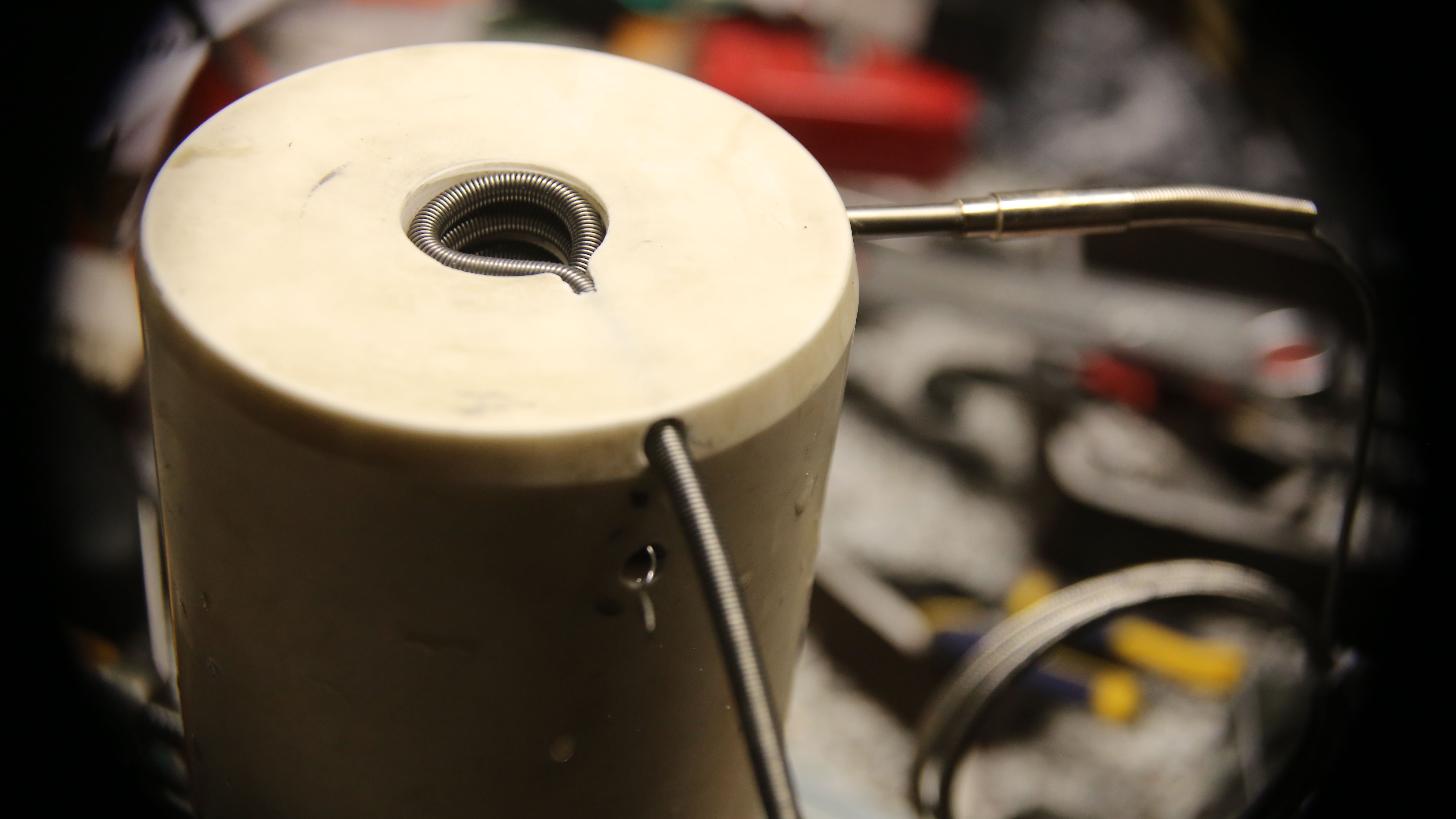
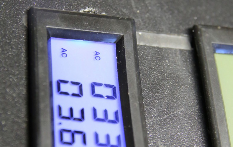
One missing step was to measure the resistance of the heating wire before it is hidden from view. This lets us keep an “eye” on the coil even when its buried in refractory. So if we get the resistance readings after packing refractory, we know for sure that the coil has not shorted out. The first coil didn’t short out, but it wasn’t packed satisfactorily.

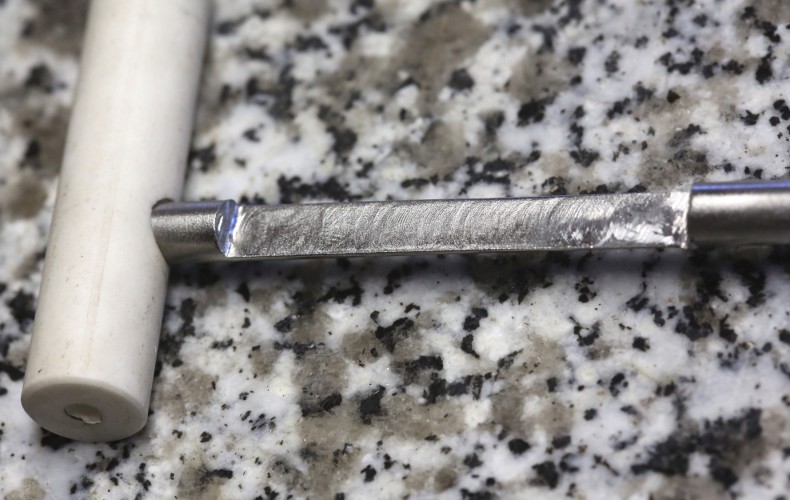
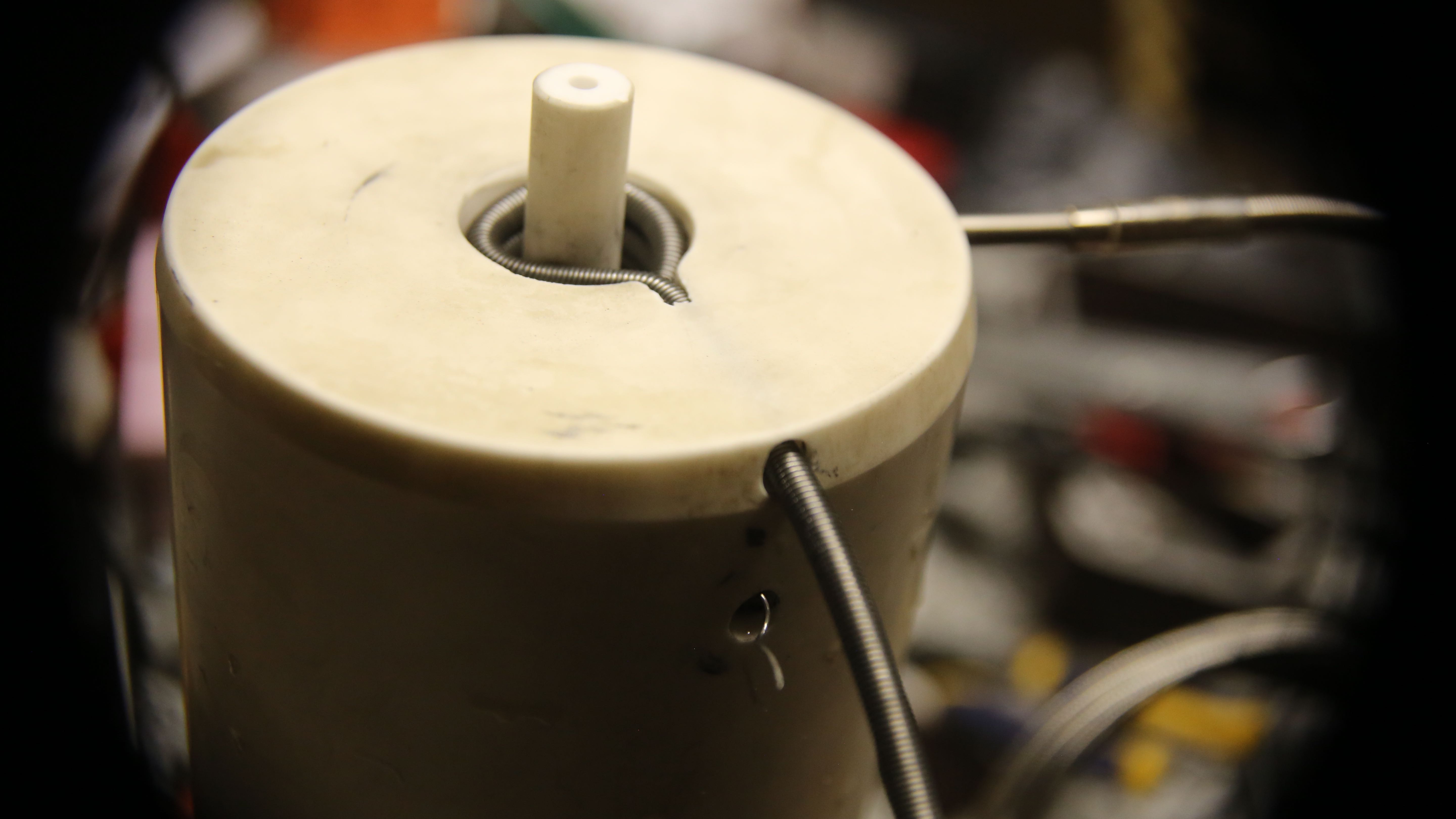
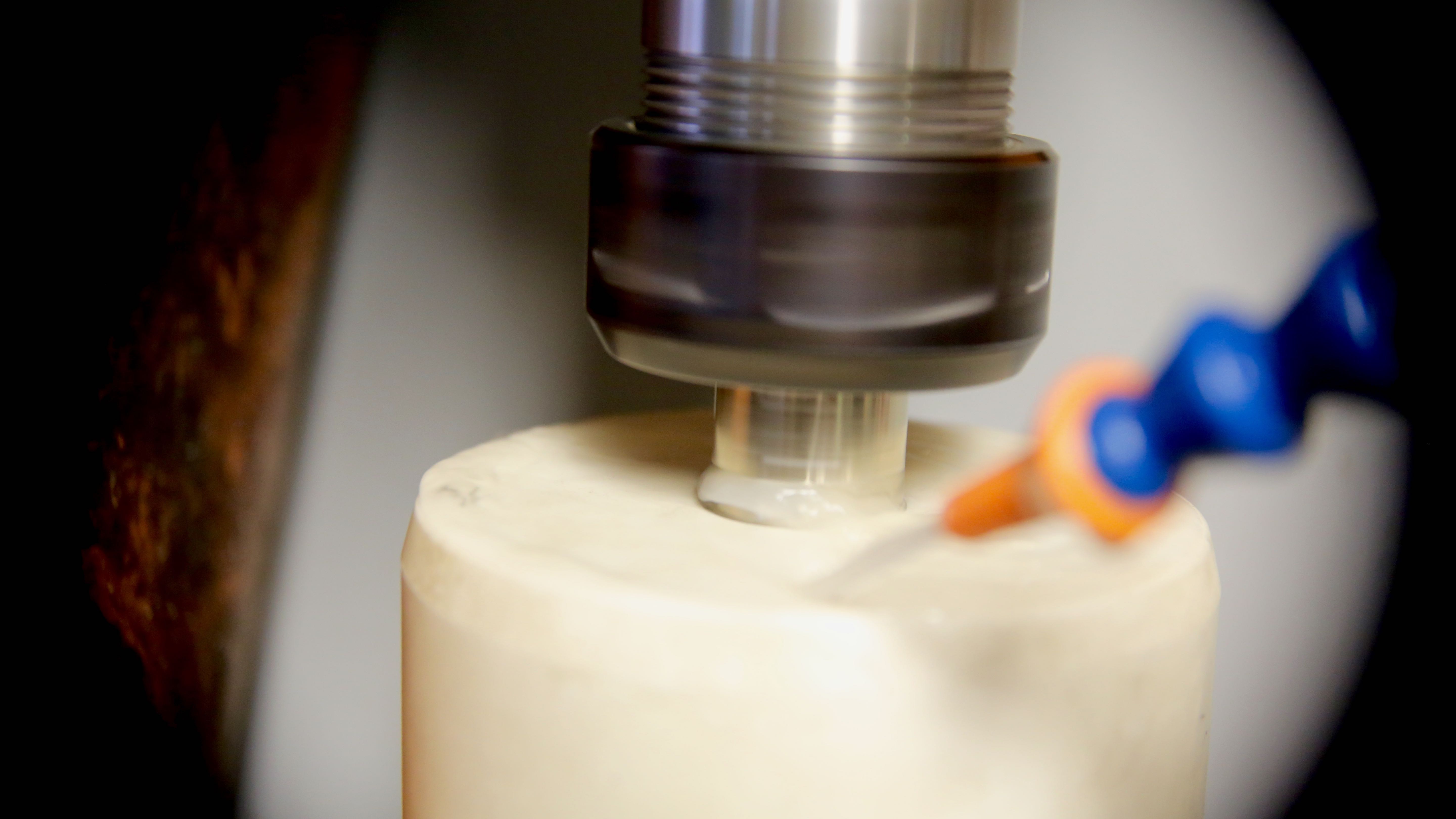
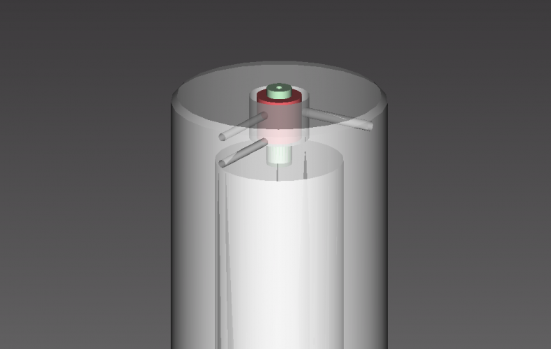
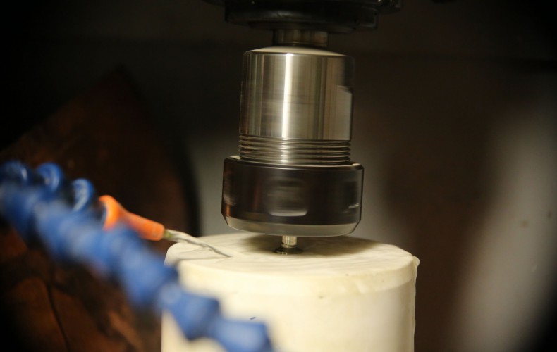
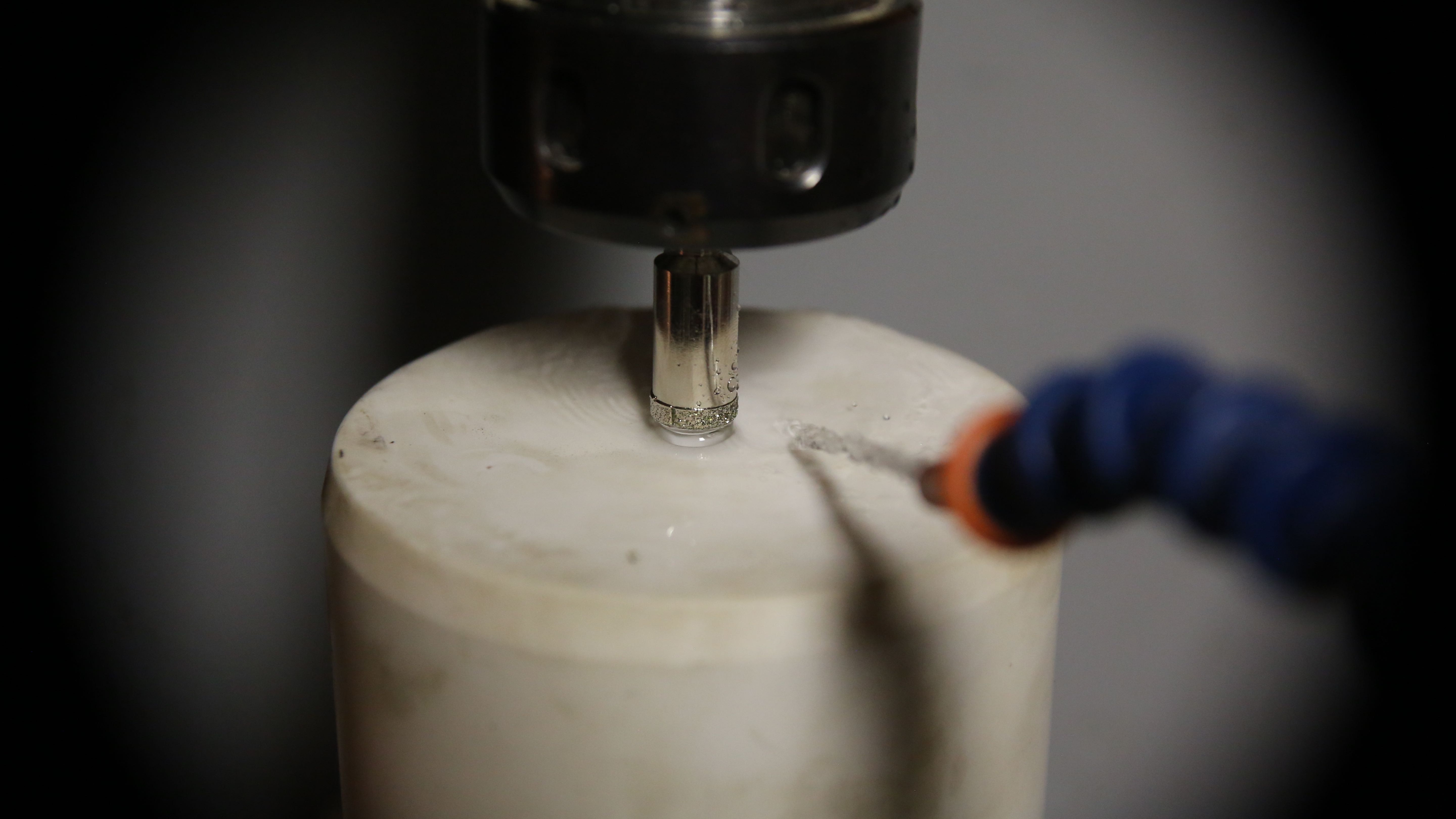
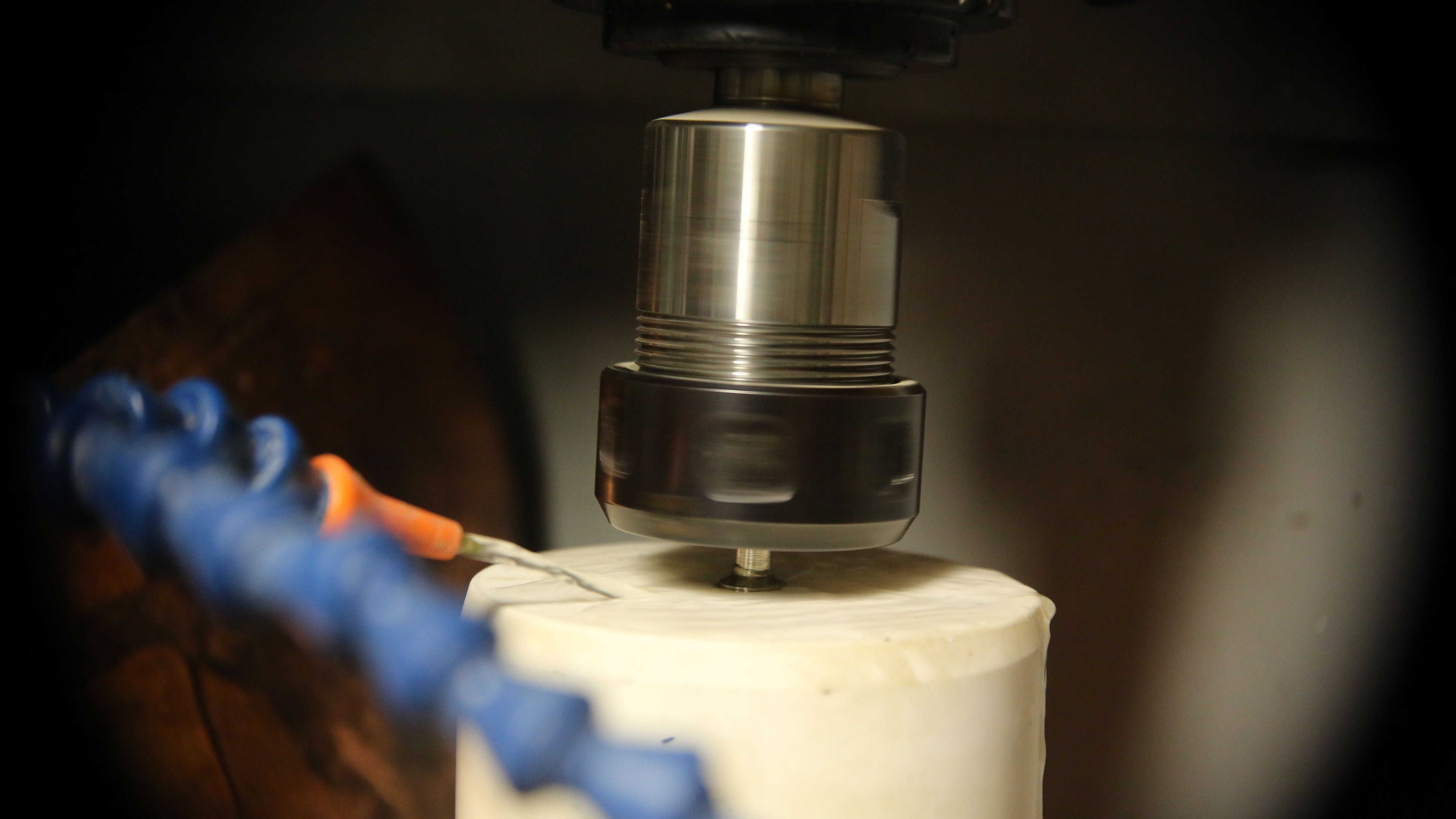
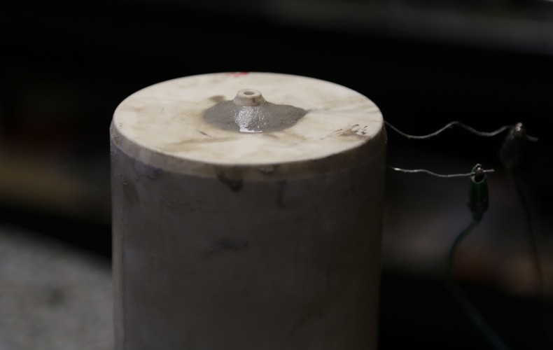
Another thing we learned is; it was difficult to pack the coil in place. So to help to that end, we decided to pre-pack the heater coil (after stretching of course). Between the proper refractory and the pre-packing we are confident this second attempt will work.

XB7A1422
Make sure to measure the resistance *before* burying the coil, and check as packed away
XB7A1424
Sorry; not very pretty. But pre-packing the coil was key
XB7A1425
Filling it up with refractory while keeping the coil from springing up
XB7A1436
So much prettier than the first one (we’re not even going to show you)


Alumina Nozzle Machining

Alumina Nozzle Machining

We are very excited to get the last hot-end machining done. It was stopping us from packing the nozzle heater in refractory, and getting this show on the road. She’s really starting to look like a lean mean glass printing machine!

XB7A1332
Cutting the nozzle to length
Boring to diameter
Boring to nozzle-tip diameter
Cutting the nozzle Chamfer
Last test fit before filling with refractory (next entry)!
Last nozzle test fit before packing the heater coil and filling with refractory (next entry)! The thermocouple probe is on the right.
Nozzle Actuator

Nozzle Actuator

One thing we really wanted from day one is to be able to actuate the nozzle. It will allow for much more complex pieces to be printed beyond single wall items (such as vases) than the glass printer as described by MIT. There are some ideas presented by the Glass Lab, though this is our stab at the task.

As eager as we are to get the nozzle glowing yellow; we took the time to put it in now. We are quite pleased with the outcome so far (to be tested of course). We wonder if aluminum and copper will be printable with this setup?!?

The main reason we bit the bullet now is the crucible assembly will be much more fragile after its all been fired, so we needed to do it now if it is to be done with our initial setup.

XB7A1299
Stainless feels like cutting butter after all this alumina (high purity sapphire ceramic)!


XB7A1298
Doh! Some more alumina to cut :/


XB7A1313
Now it is open; now it is closed! Repeat. On retract g-code that is.


XB7A1304
Water tight fit! Should hold glass 🙂


XB7A1300
Nice and slim design – doesn’t take much from the very precious under nozzle clearance


XB7A1310
This will connect to a stepper driven rack and pinion. To be continued.
Final Crucible Machining

Final Crucible Machining

Today was a big day for the 3D printer! The machining for our lovely new crucible is now complete.

Shown here is a test fitting of the nozzle coil at last!

Not to fear; it will get pulled to spec and properly spaced before we will it with 3000F refractory. In fact, that will be the next entry as far as the crucible goes at least.

Then – we will be all set for the first firing! Whoooo-hoo!

XB7A1283
Coil test fit without nozzle
XB7A1285
The probe on right side back is the thermocouple and nozzle heater coil entry and exit are near center foreground
Lost PLA Casting

Lost PLA Casting

When we need a custom part around here, often we will print it out of plastic and then perform our lost PLA process to the print transforming it into a flawless metal copy.

Cast directly from 3D print, with no machining (other than vent cut off)
PRINT CHAMBER FRAME PART II

PRINT CHAMBER FRAME PART II

The frame is about complete now with working (drop down) front door. You can see our 14″ ceramic window to be installed in our door.

The build platform is a 21″ kiln shelf that MIT’s Glass Lab suggests that glass will stick nicely at print chamber temperatures (800F) and pop off when cools. We can’t wait for that!

Nozzle Coil Hole Machined

Nozzle Coil Hole Machined

We got most the machining of the crucible done now. We just need to poke 3 small holes in the sides of it and we are done machining the very hard Alumina!

That said we have to wait for the bits to arrive – should be tomorrow. Then we can put the heater coils in and test fire it pretty soon after.

Let the glass flow, let it flow!

Note the nozzle currently protrudes too far – it will get cut in the near future.

The rest of our printer is currently sitting around waiting for this super hot end and we can’t wait to let it have it.

XB7A1241

Steel Crucible Mount

Steel Crucible Mount

We had some much needed steel arrive today. The bands around the crucible will be filled with mostly insulating refractory and some steel to connect and drive her ’round and ’round.

This is going to be one HOT End! Woot!