Our precious crucible cart has undergone its final transformation into what will likely become the key element of our glass printing machine. Unlike portland, refractory does not use good ol’ H20 for its chemical bound, so for refractory, firing is a key step.
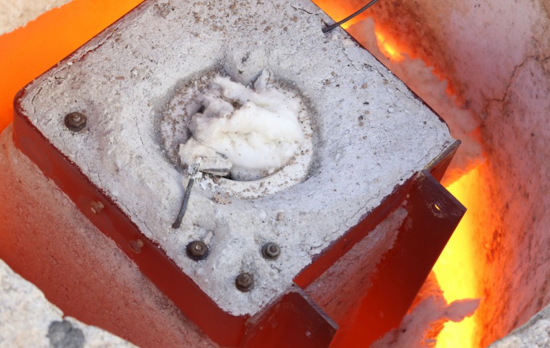
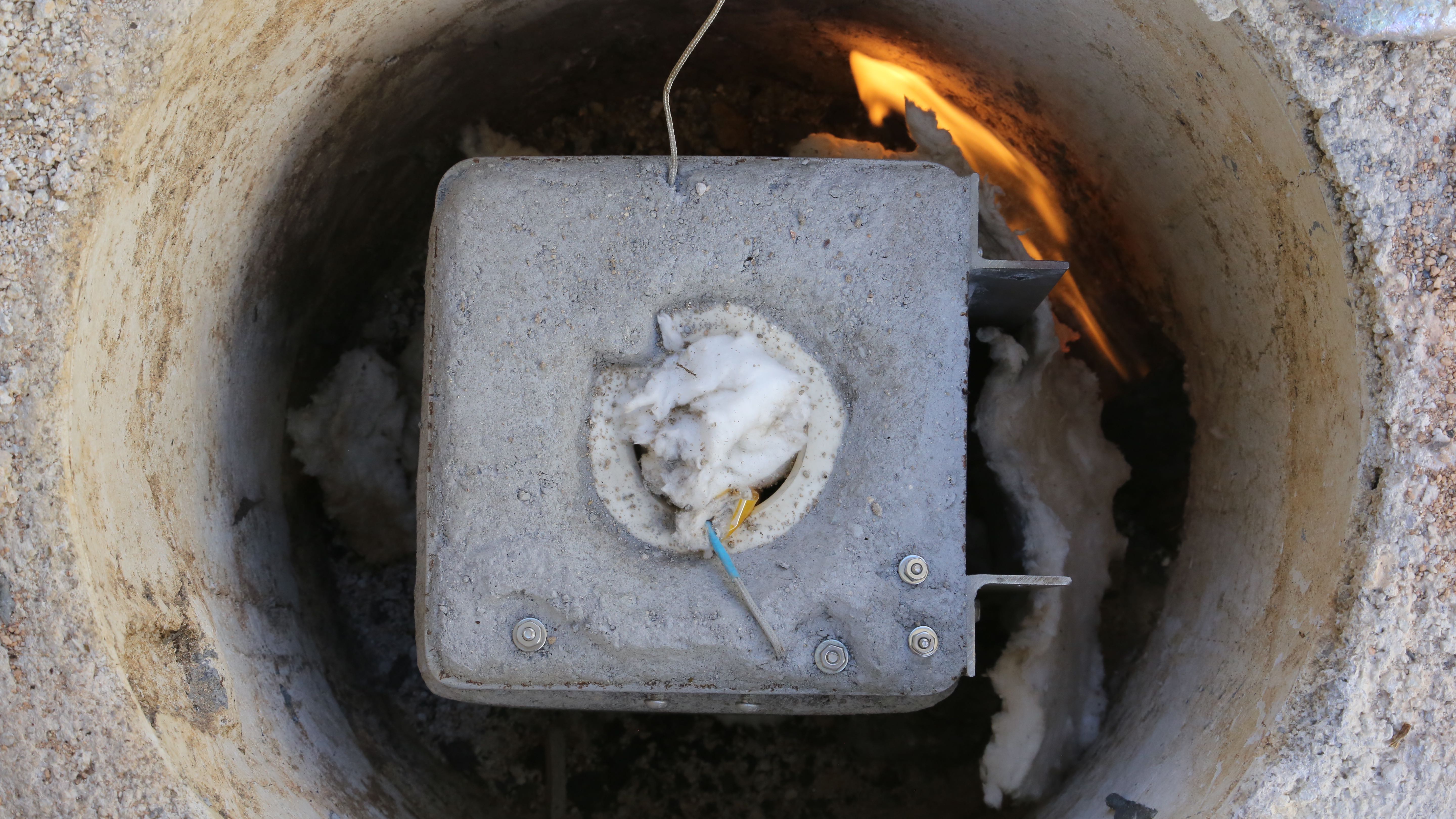
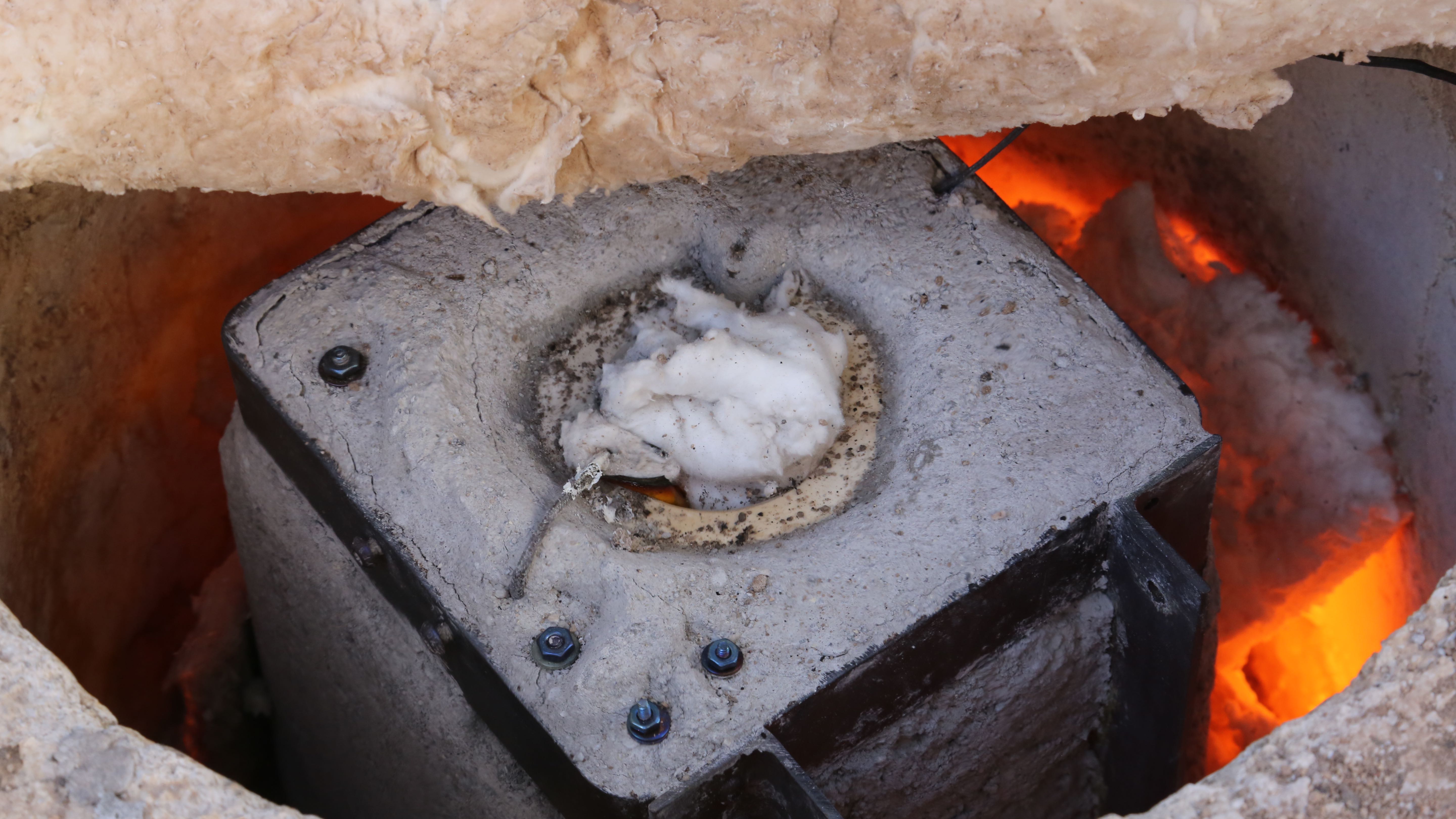
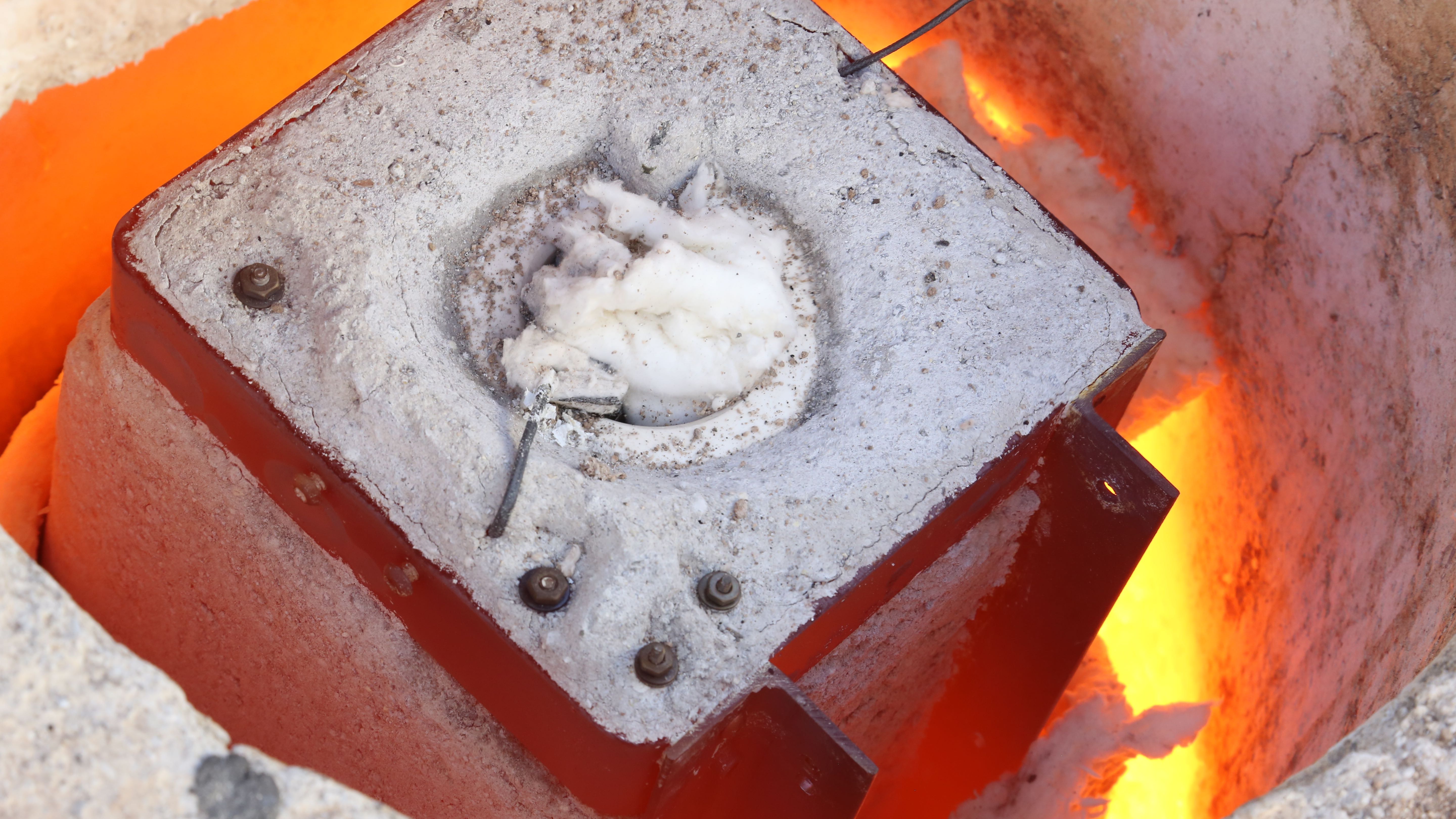
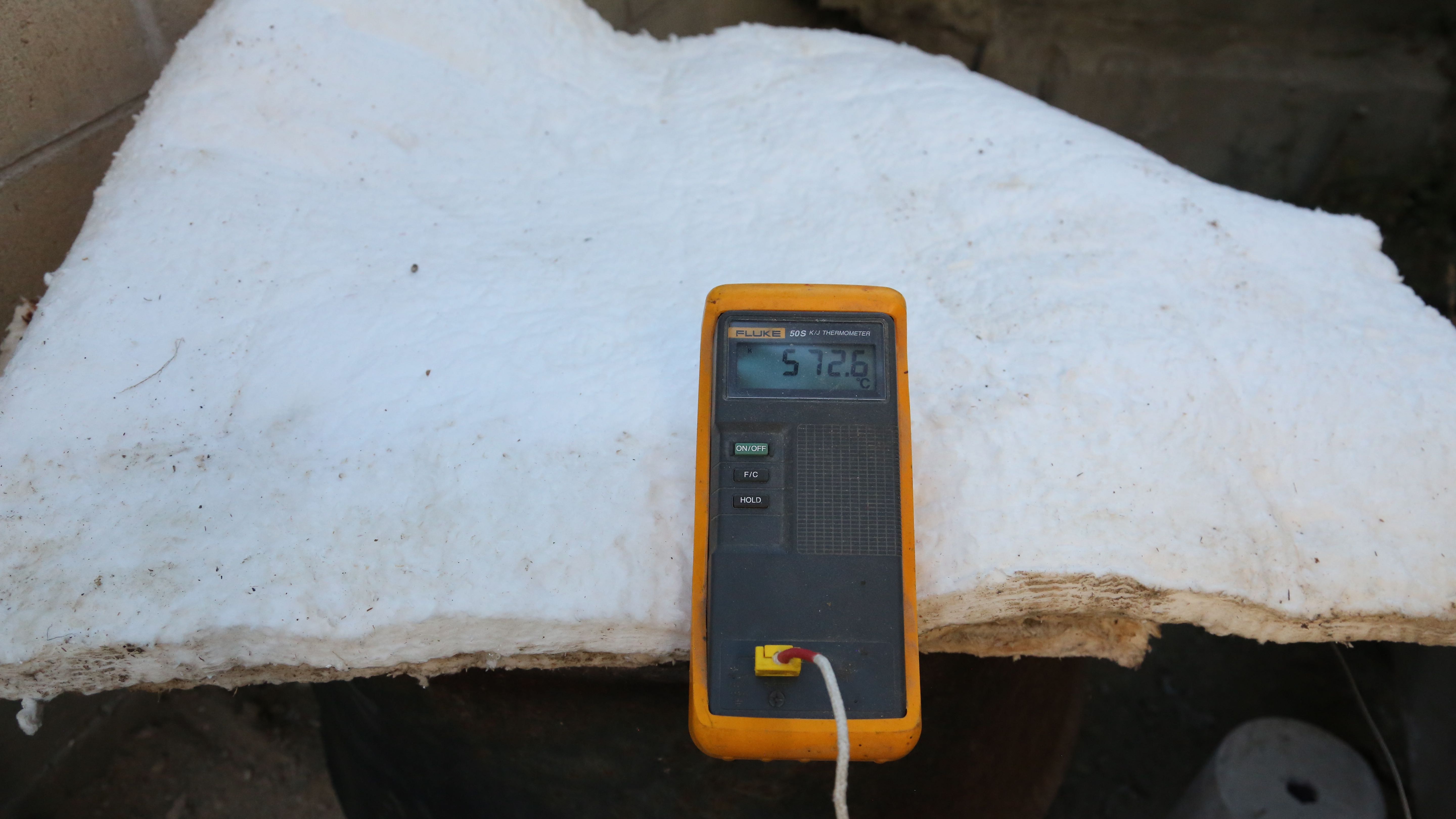
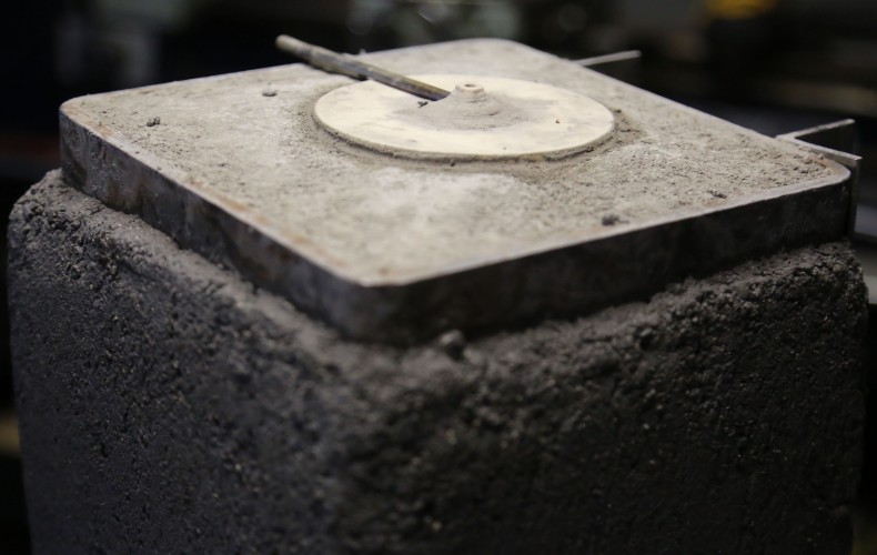
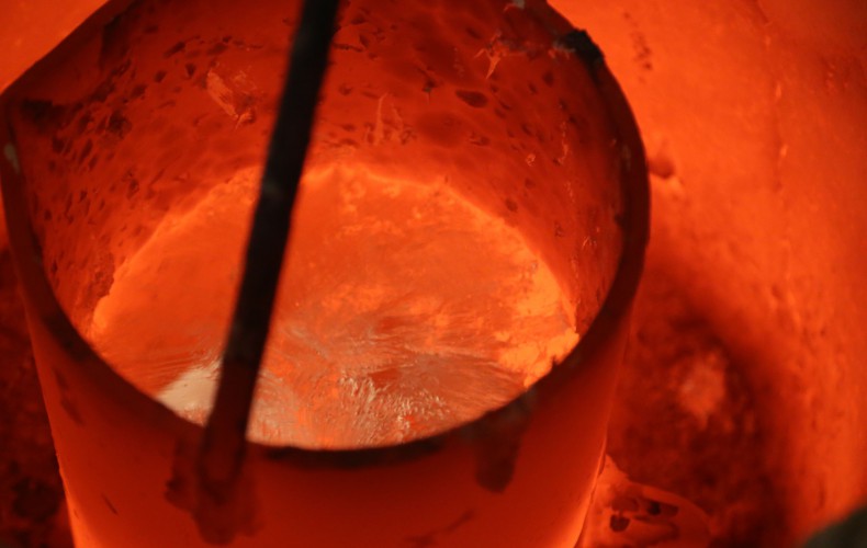
Furnace Fractal? After we slowly ramped the temperature of a kitchen oven up to 400F it was time to put it in our furnace to gently ramp up to over 1200F. If the refractory is heated too quickly (first time) you run the risk of steam explosions ruining all your hard work or the refractory not maturing to full strength. Starting flame shown.Getting warmer. Added some fiber blanket in the back to shield it from direct flame.Warmer!Hotter. Our crucible thermocouple reading was around 800F – we need it up around 1200F soaked all the way through…There we go. Now our refractory is a lovely pumpkin color. We’ll let her bath in it for a while, but reduce BTU input – we don’t need it any hotter. Well that is until she is operating under her own power that is of course.Desired tempter reached and maintained for a while.Cooked until perfectionResting temp at 572C (1061F). Covered the furnace with extra blankets to let some of that trapped heat soak all the way through and slowly cool overnight.
Next time you see our crucible cart it should be mounted on our machine!
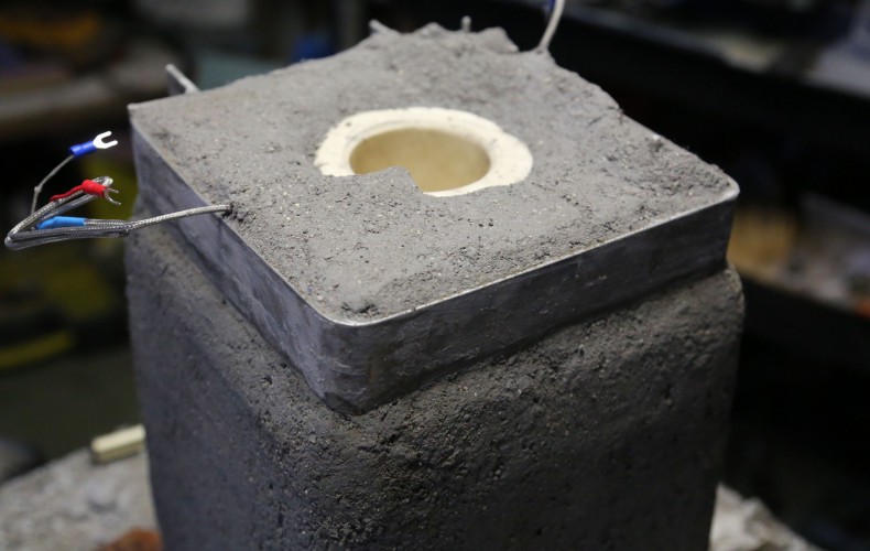
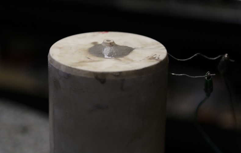
One last chapter before we can begin our crucible cart’s dryout schedule: the top. We need a bomber top to handle ladling of molten glass blobs into the crucible as well as way to fix the loose electrical terminals. The insulating refractory won’t cut it in these departments so its time for some more 3000F rated refractory to coat on top.
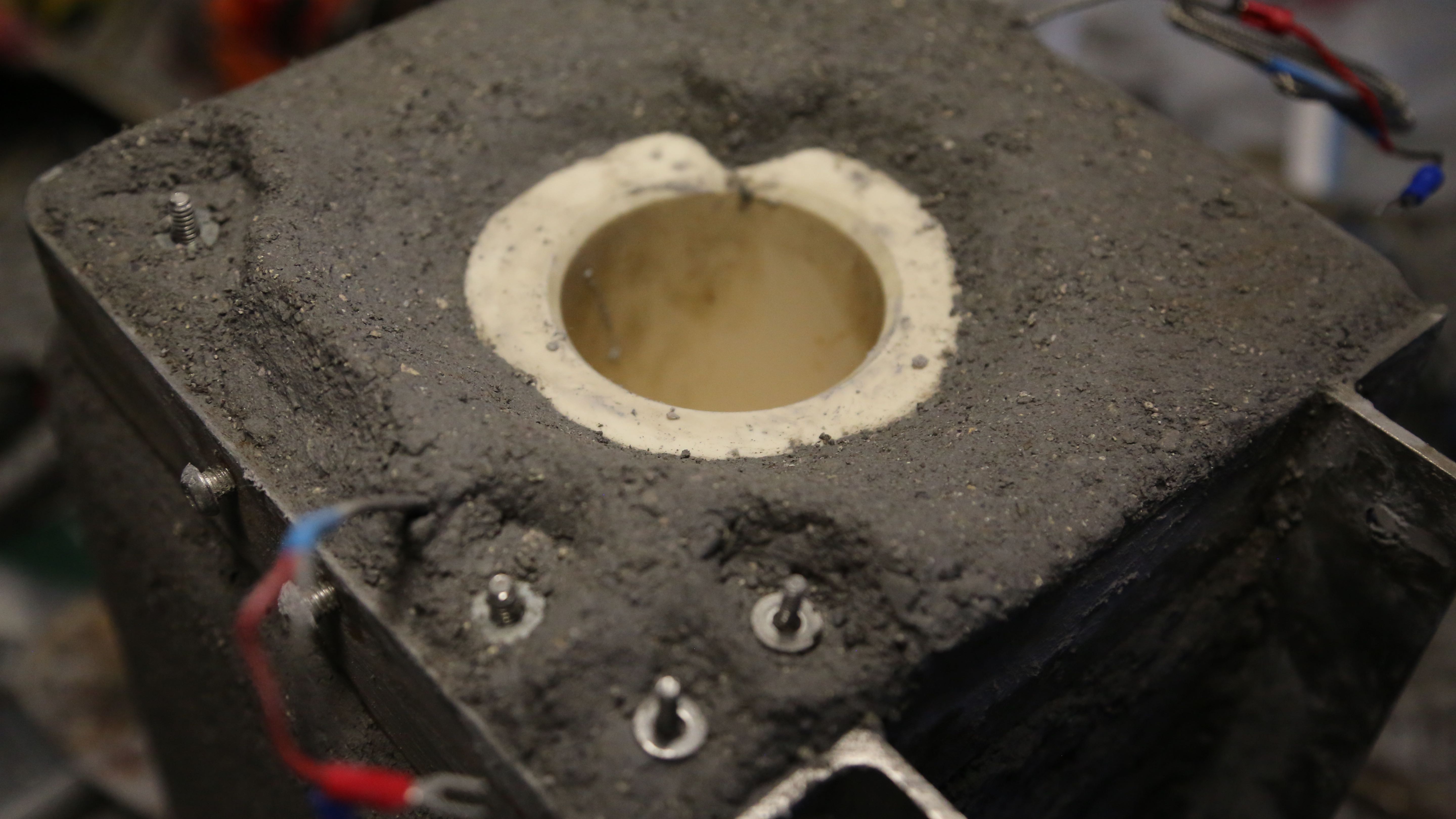
Here she is flipped over for the first time the following day. Looks good except the top.Before we scrapped a little more insulating refractory off. Loose wires wires evident in background.We attached stainless steel bolts to the 4 loose electrical leads (crucible heater and nozzle heater). Much better already!All the electrical leads now have nice firm bolts to attach the leads to. They are somewhat protected from ladles of glass by some additional refractory strategically placed. The notch evident is to shield the crucible’s thermocouple.Now we have to wait (again) before putting the whole crucible cart into an oven to meet its firing schedule. To be continued…
After its fired we can get it mounted to the machine and should be showtime!
Now that we have that big (potentially) hot heater coil wrapped about our crucible, its time to give her some insulation to keep those precious BTUs where we want it – melting glass (or whatever else we may find ourselves melting with our new contraption – mooohahaha).
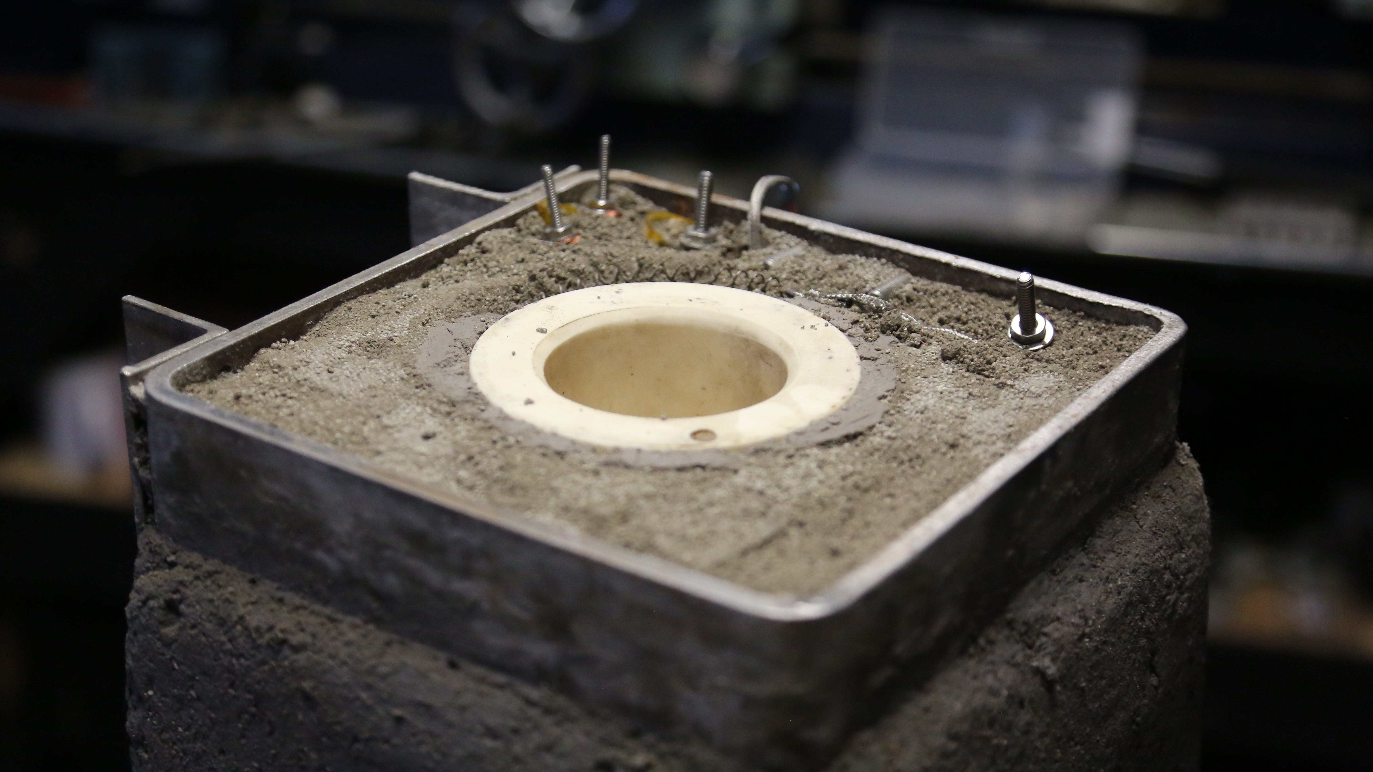
Alright, so now after carefully placing our crucible cart onto our vibrating table we clamped forms around the sides ready for filling. In all places where there was potential wood contact, we covered said wood with plastic bags to prevent it from adsorbing an unfair of moisture from the curing refractory.
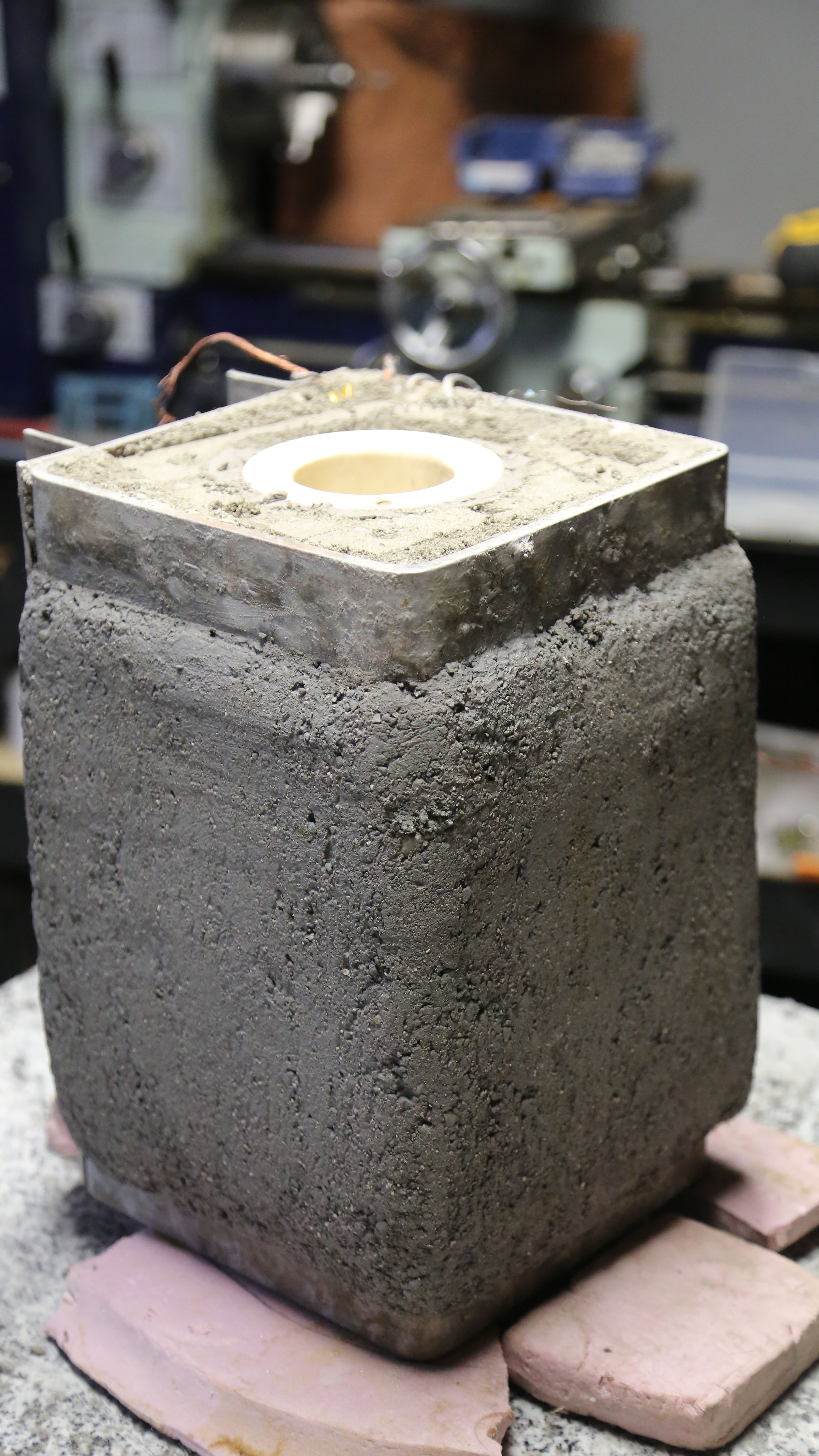
On our vibrating table – ready for filling with 2500F insulating refractory.Refractory isn’t portland – its typically applied much more dry – very dry.All filled up, now it has to sit for at least 24 hours covered with plastic.We scrapped off some of the frail insulating 2500F refractory after it came out of the forms. Then we troweled on a generous shell of much more durable 3200F refractory. Then wrapped with saran wrap for 24 hours.
Then we get to flip it over and finish the top side – next episode.
Of course, if we are to melt glass, we are going to need some heat, a whole lotta’ heat indeed! So we are pleased to finally outfit our crucible a 220V 2KW heat coil and packed in a jacket of 3200F rated refractory.
Heater coil wrapped fairly uniformlyThe first patch of 3200F refractory.All wrapped up nicely, ready for cart fitting.
As we were saying; cart fitting. We added some ceramic blanket wire insulation in the iffy spots (the tape will burn away but the protected space will remain).
Next up – fill this baby with some insulating refractory to keep our needed heat in.
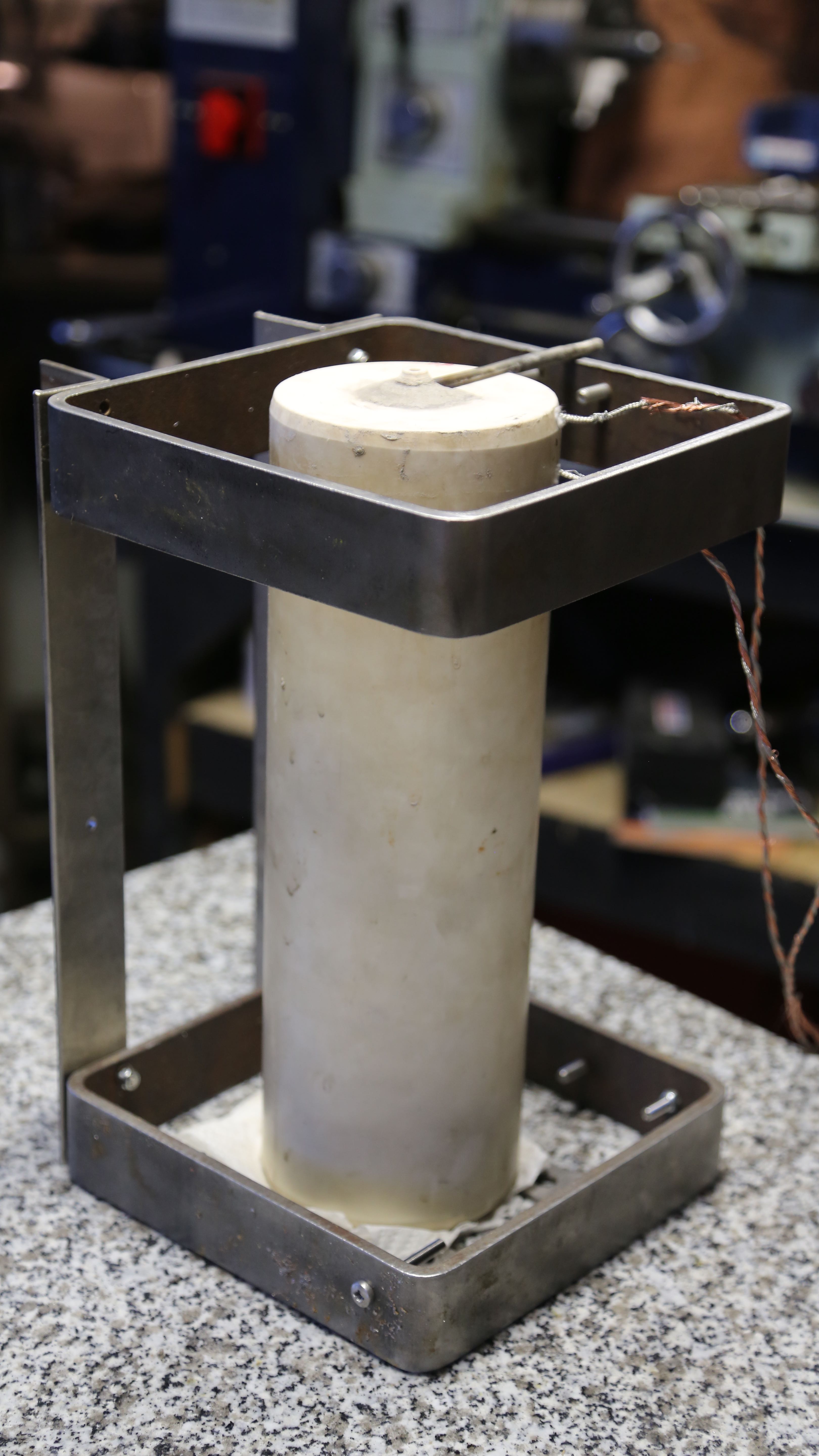
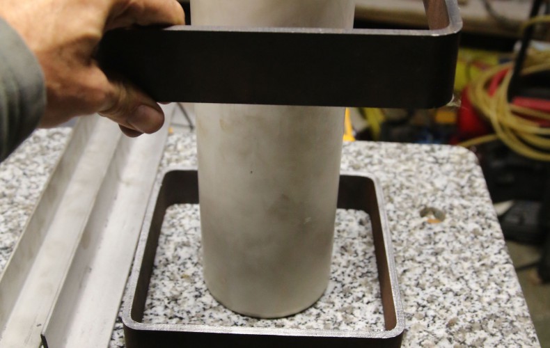
We got the cart all built today. The crucible isn’t much good if we can’t steer it around, and that is the the cart’s primary task. The secondary task is to provide a frame that will fill with high temperature insulation (refractory).
The third task is to provide a thermal heat break from the 2000F crucible. We selected stainless steel for that task and in addition, the stainless doesn’t make full contact with the steel it will be mounted to. So the stainless is about 1/4″ away and only make contact where it is bolted.
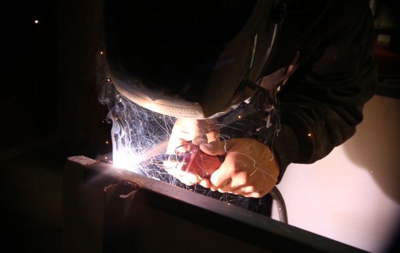
Fitting the cart to the steel that will drive itAll ready to be filled with refractory! We added some extra bolts so the refractory cannot possibly slide out. We connected braided stainless steel to the nozzle heater leads and for good measure after a short distance started weaving copper around the stainless (it should be far enough from the crucible to not melt).
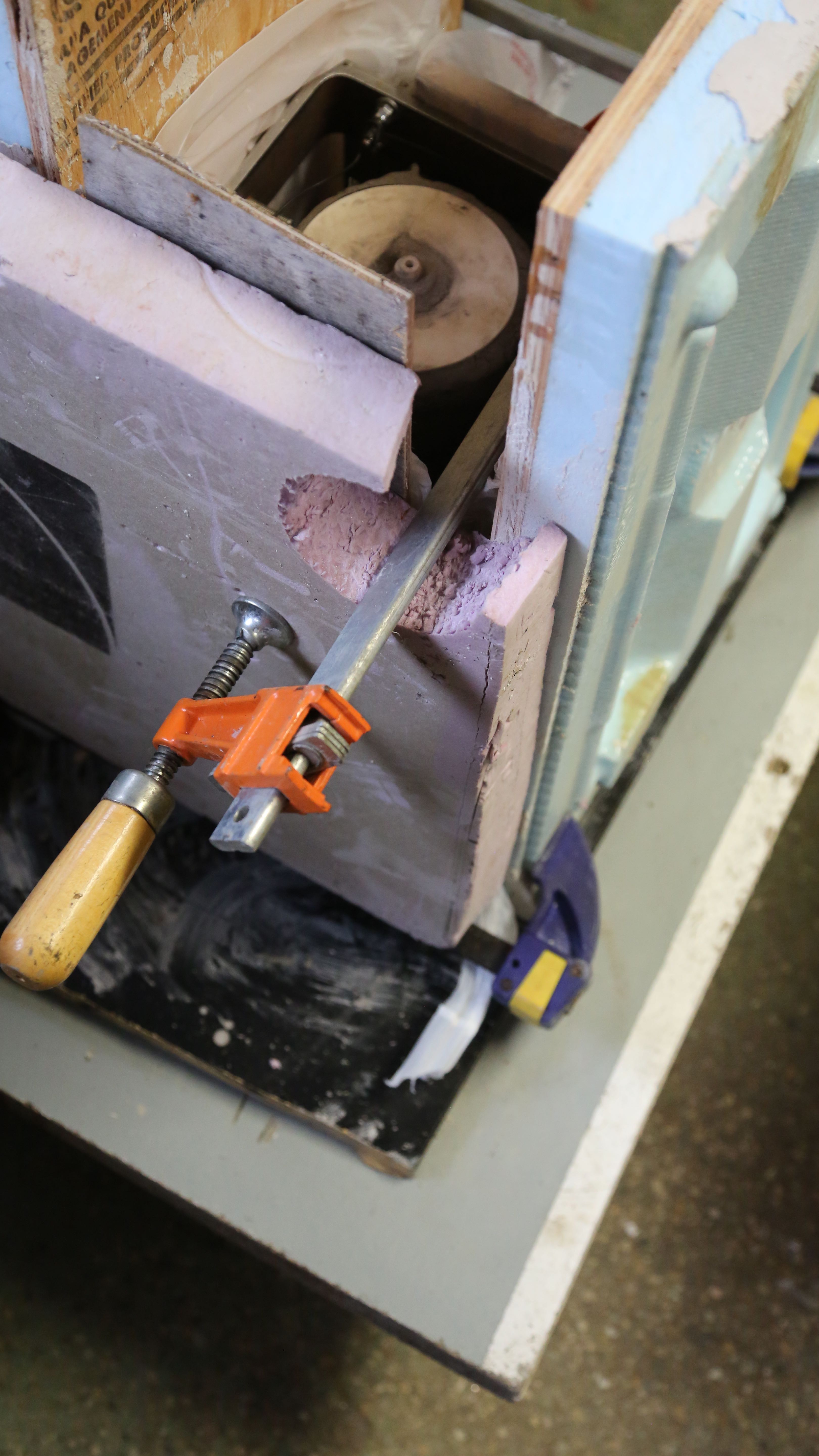
Our first nozzle heater coil attempt failed miserably. The refractory selected for the task was far too course and we were unable to fill the nozzle cavity properly. So when it heated up, the heater coil sagged and shorted out. But – we did learn from our mistake(s)!
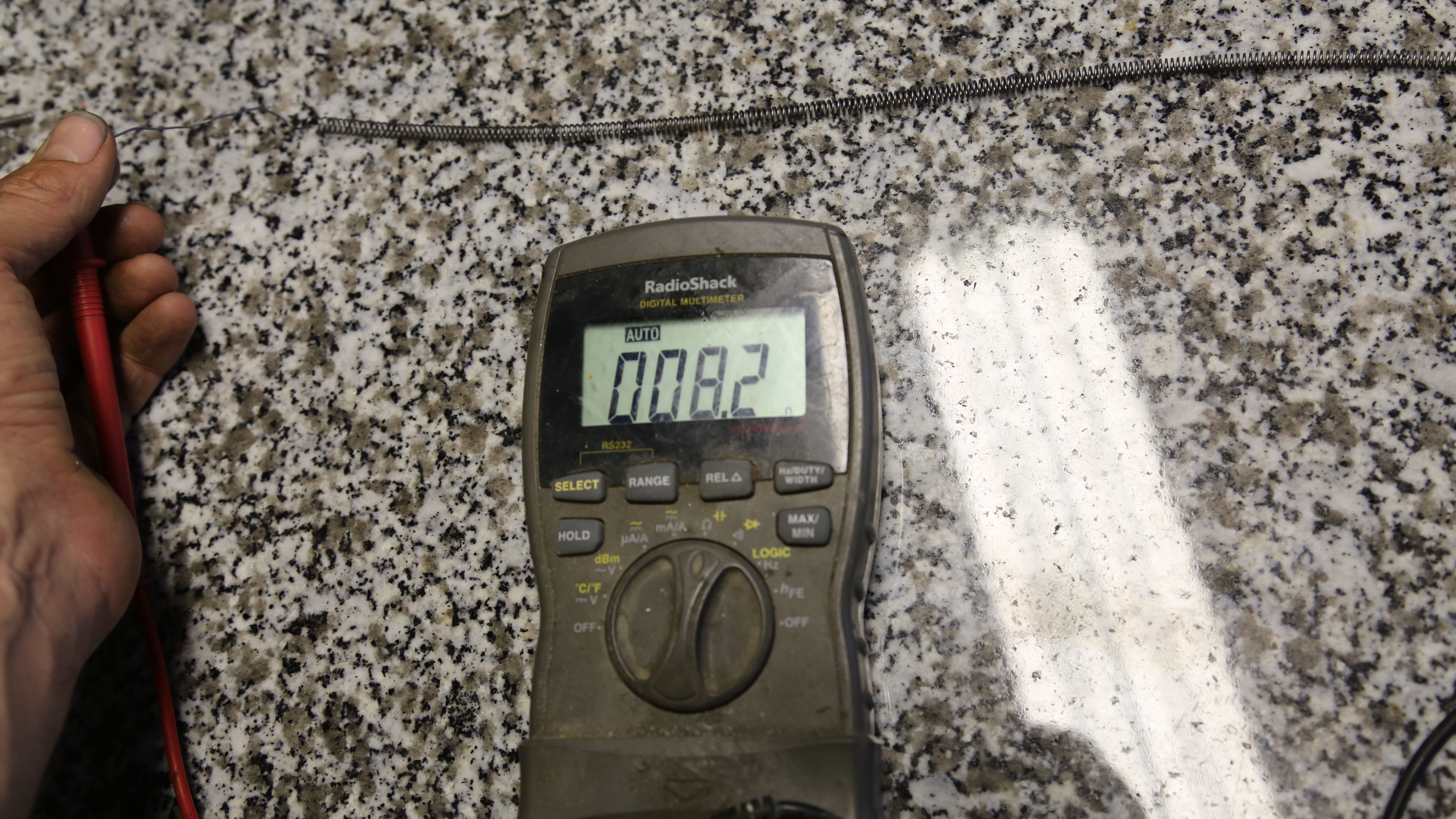
One missing step was to measure the resistance of the heating wire before it is hidden from view. This lets us keep an “eye” on the coil even when its buried in refractory. So if we get the resistance readings after packing refractory, we know for sure that the coil has not shorted out. The first coil didn’t short out, but it wasn’t packed satisfactorily.
Another thing we learned is; it was difficult to pack the coil in place. So to help to that end, we decided to pre-pack the heater coil (after stretching of course). Between the proper refractory and the pre-packing we are confident this second attempt will work.
Make sure to measure the resistance *before* burying the coil, and check as packed awaySorry; not very pretty. But pre-packing the coil was keyFilling it up with refractory while keeping the coil from springing upSo much prettier than the first one (we’re not even going to show you)
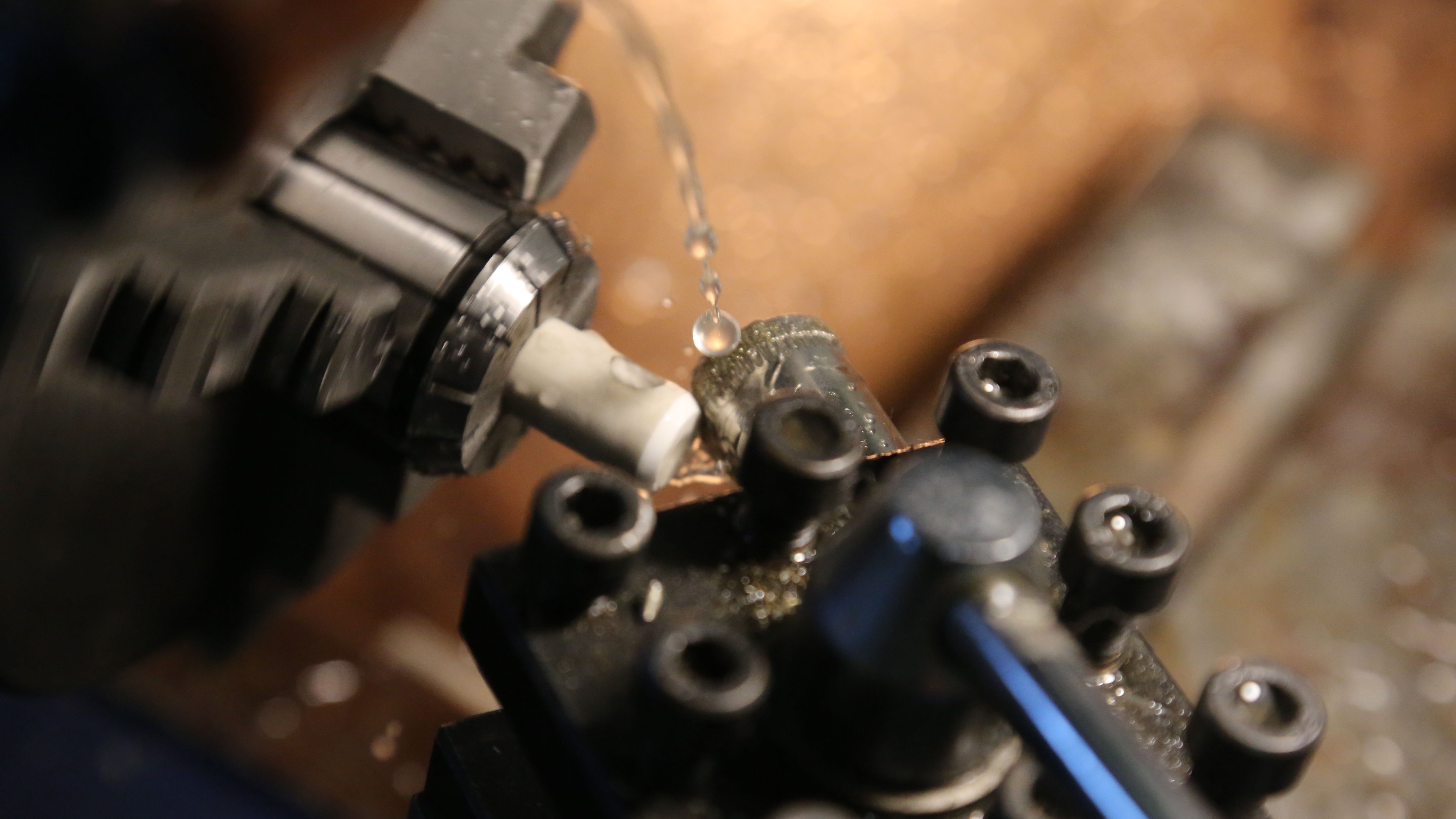
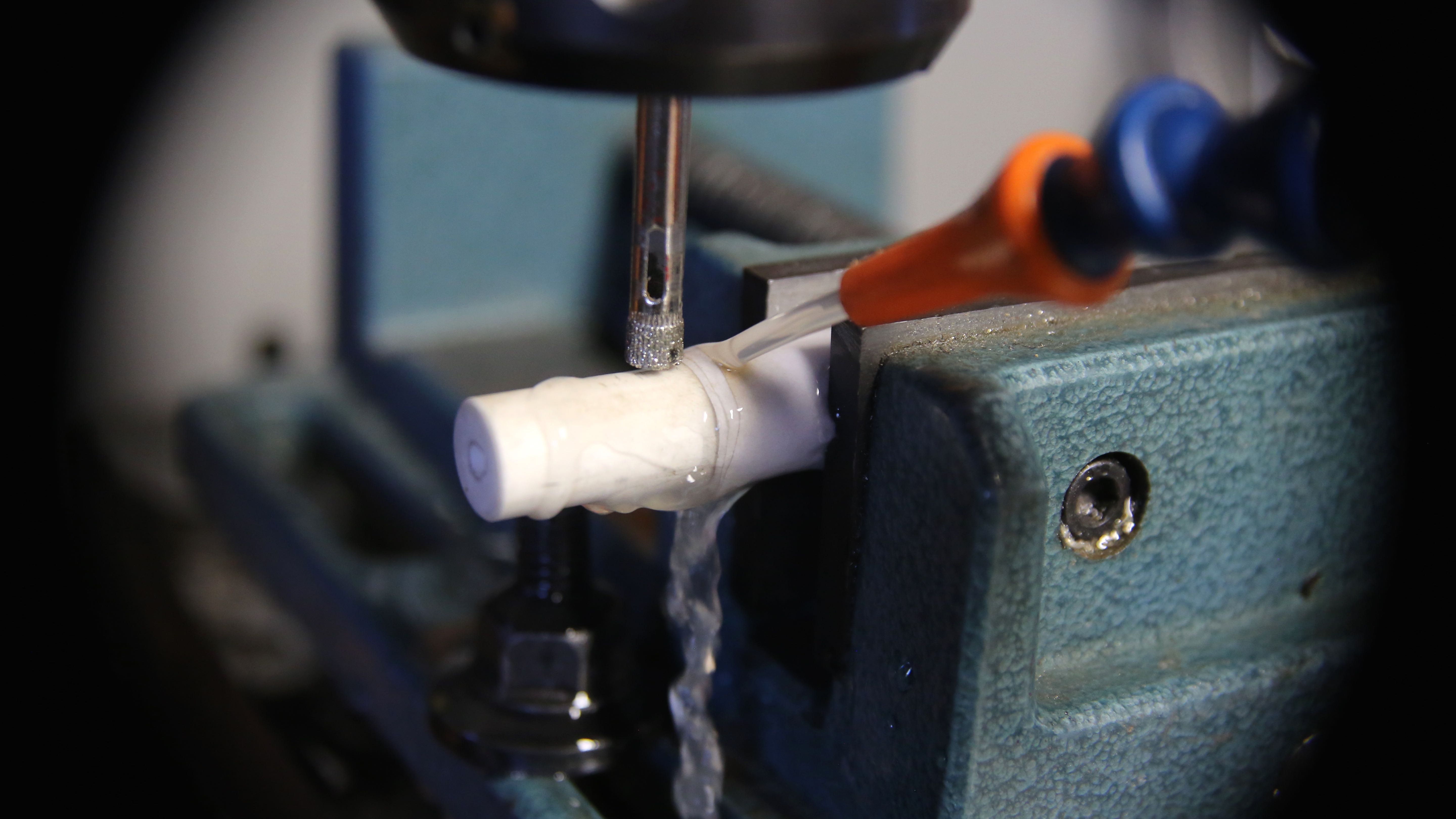
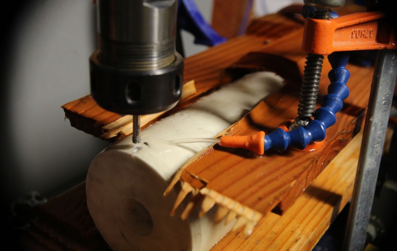
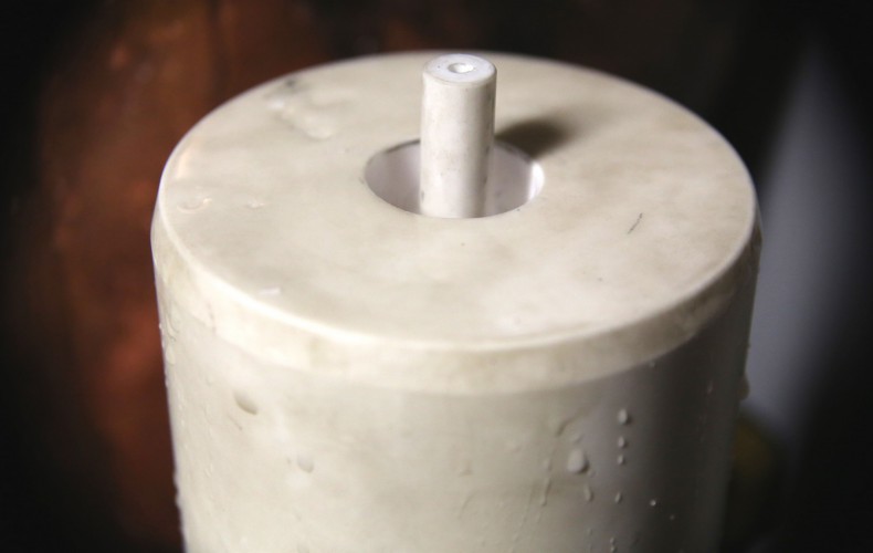
We are very excited to get the last hot-end machining done. It was stopping us from packing the nozzle heater in refractory, and getting this show on the road. She’s really starting to look like a lean mean glass printing machine!
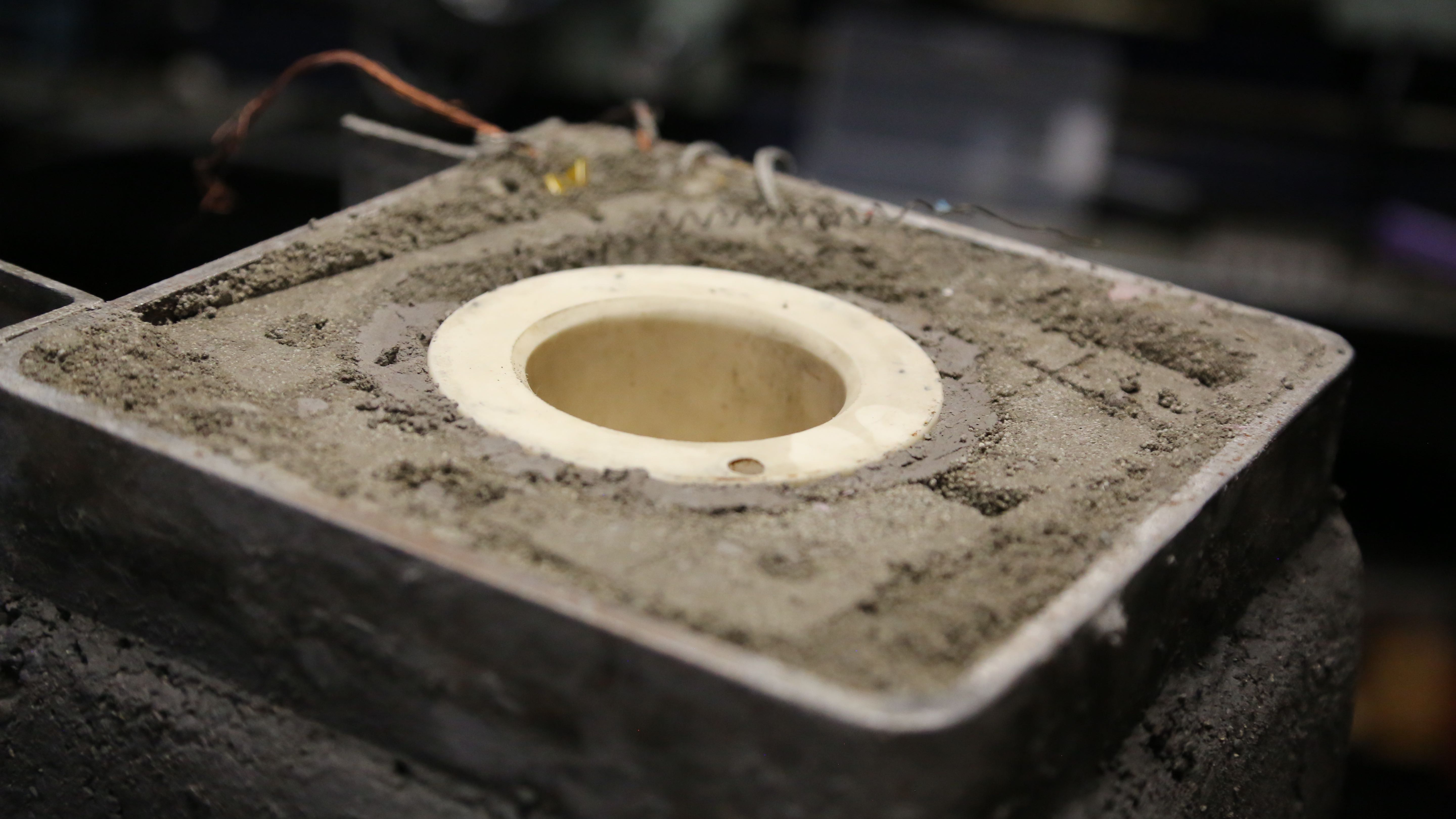
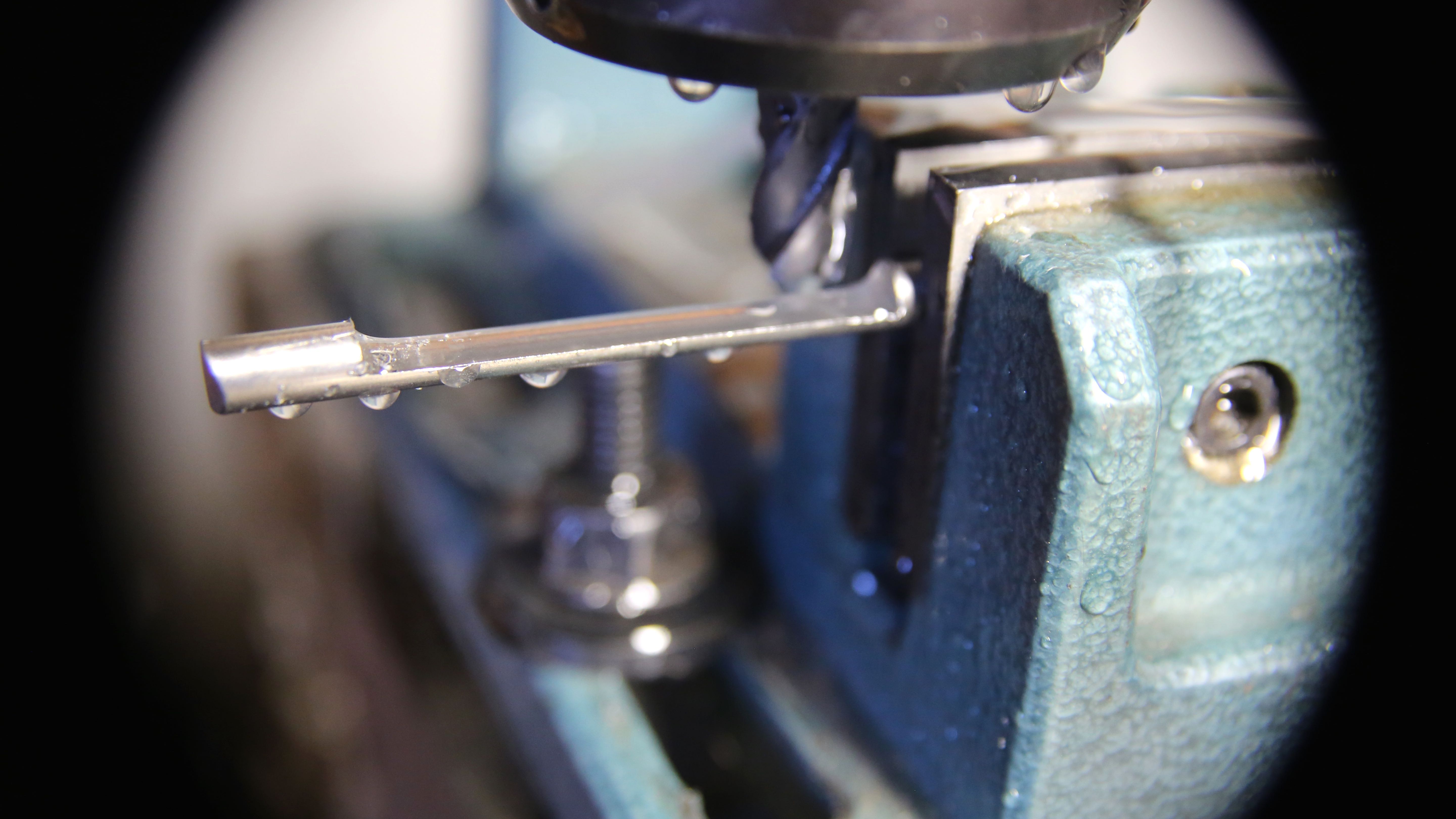
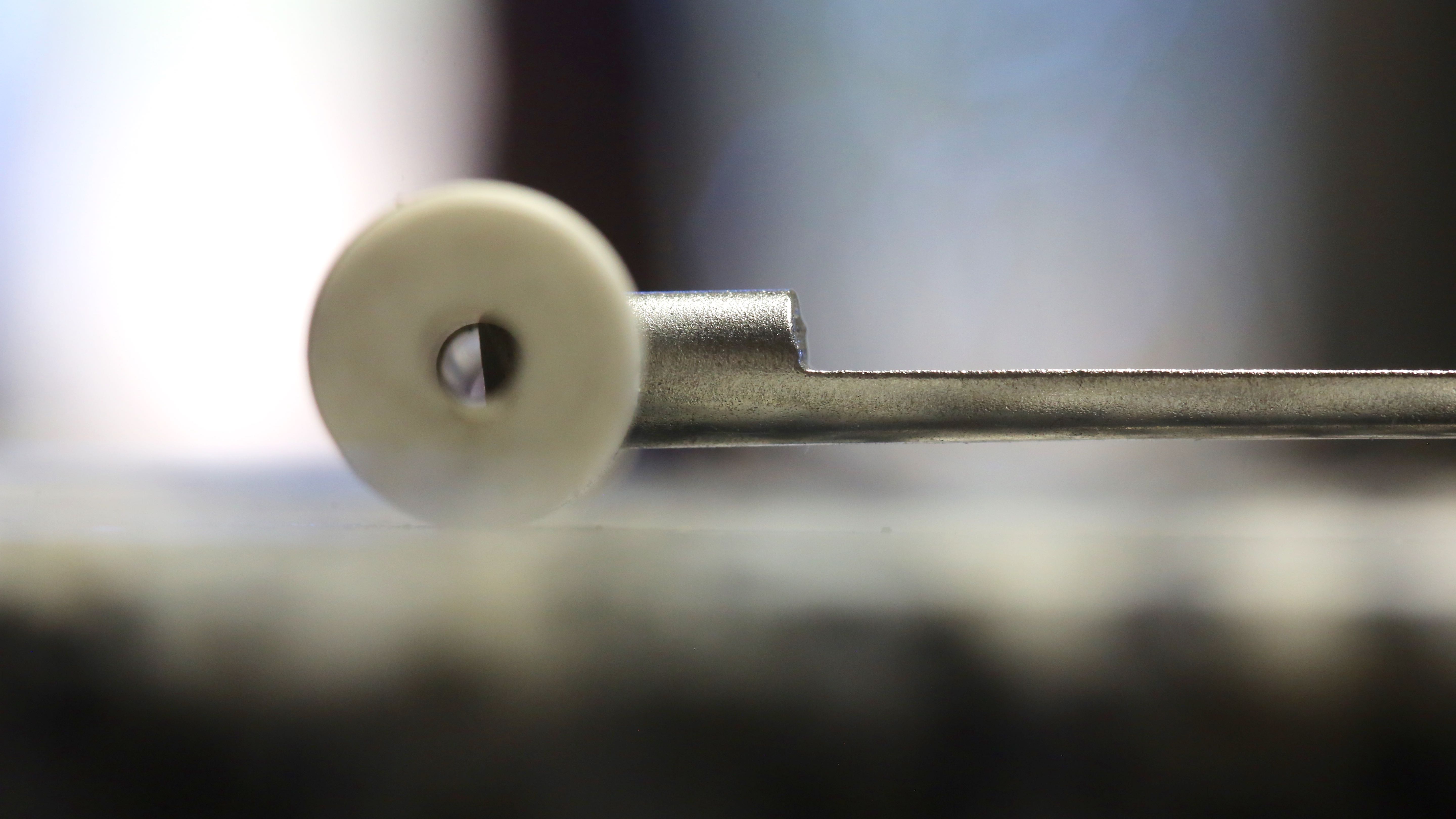
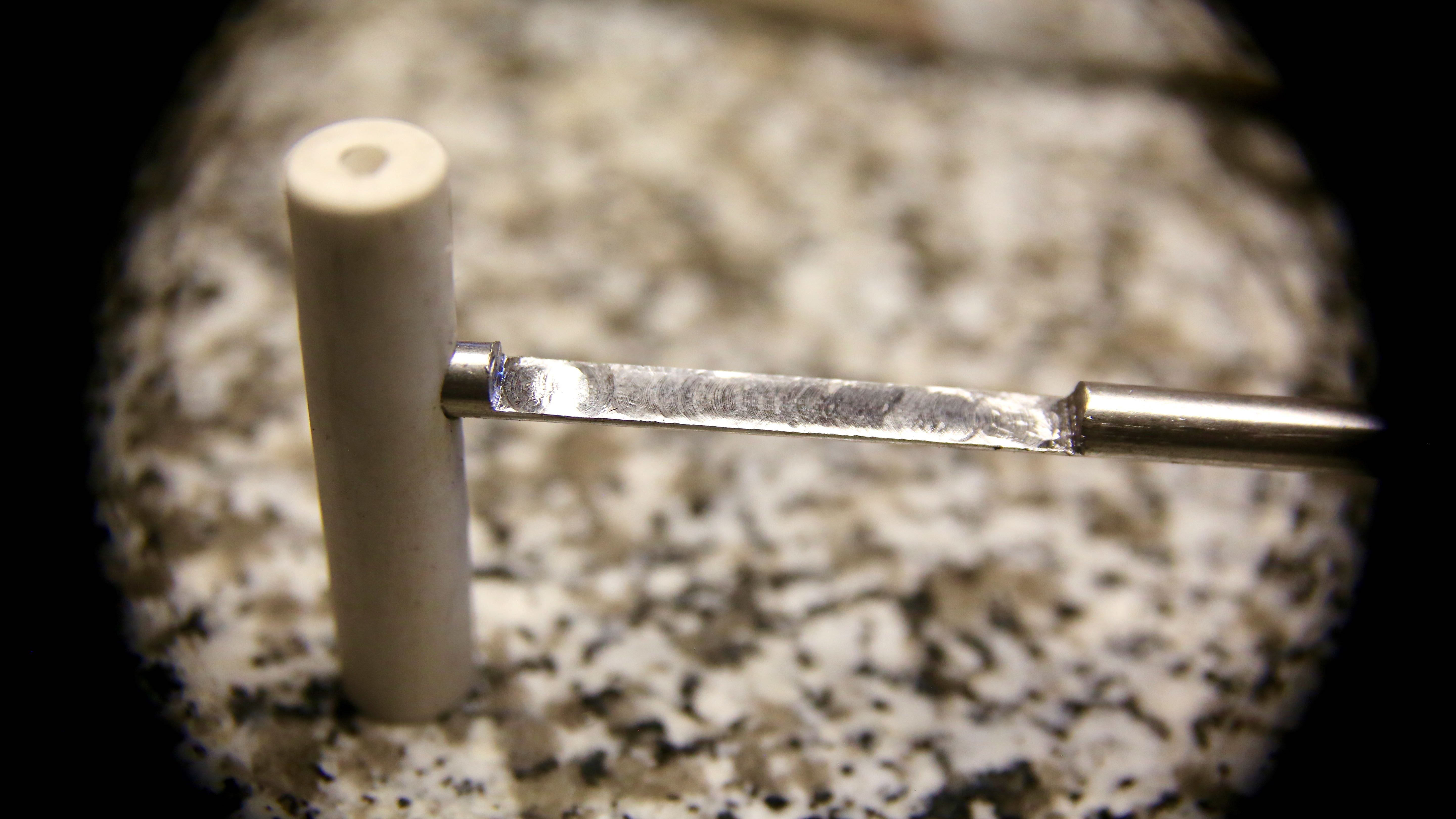
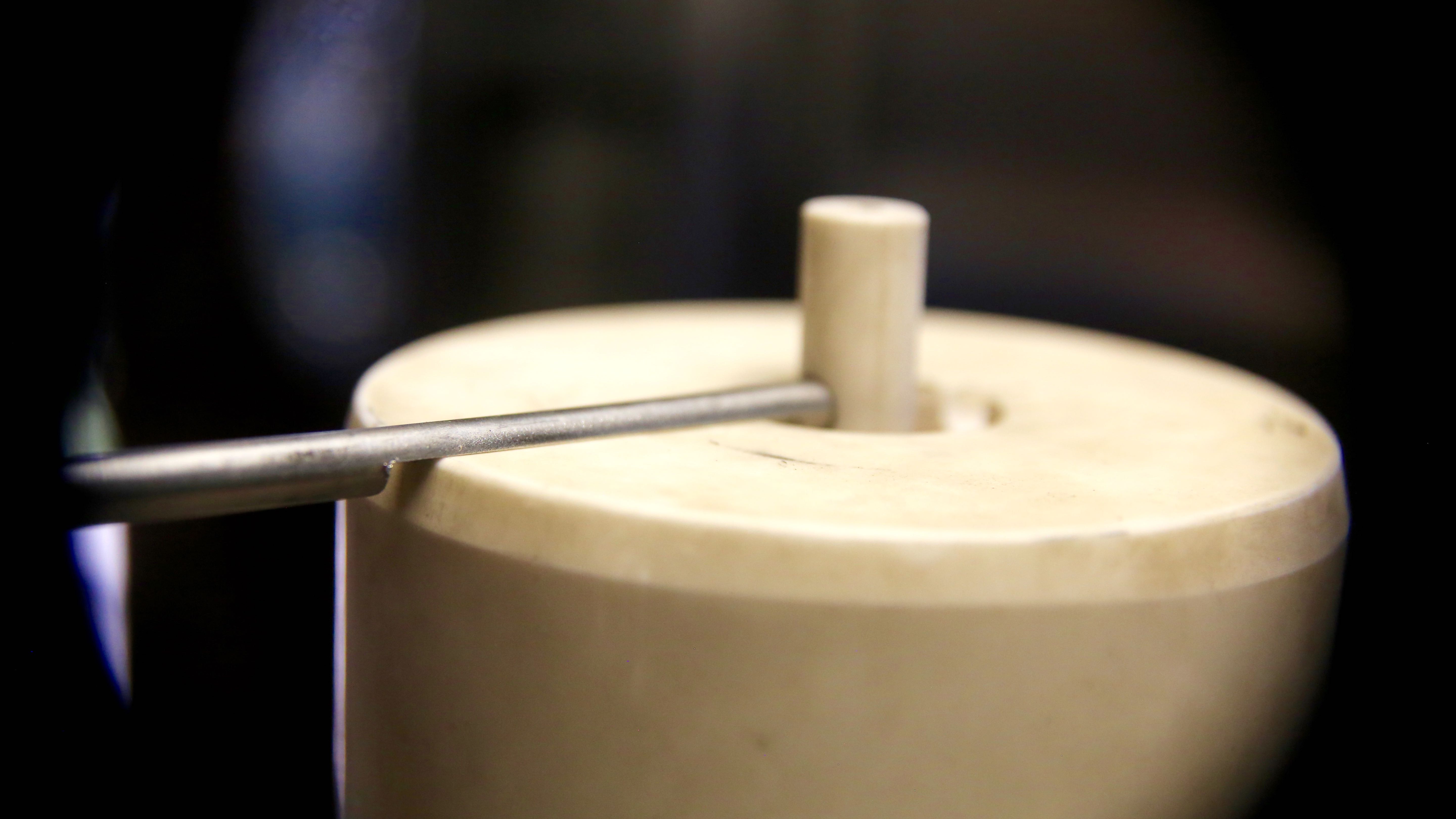
Cutting the nozzle to lengthBoring to nozzle-tip diameterCutting the nozzle ChamferLast nozzle test fit before packing the heater coil and filling with refractory (next entry)! The thermocouple probe is on the right.
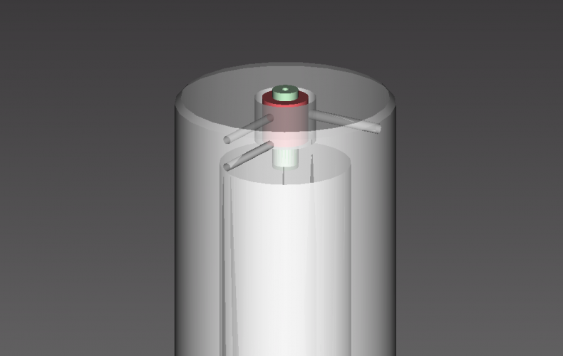
One thing we really wanted from day one is to be able to actuate the nozzle. It will allow for much more complex pieces to be printed beyond single wall items (such as vases) than the glass printer as described by MIT. There are some ideas presented by the Glass Lab, though this is our stab at the task.
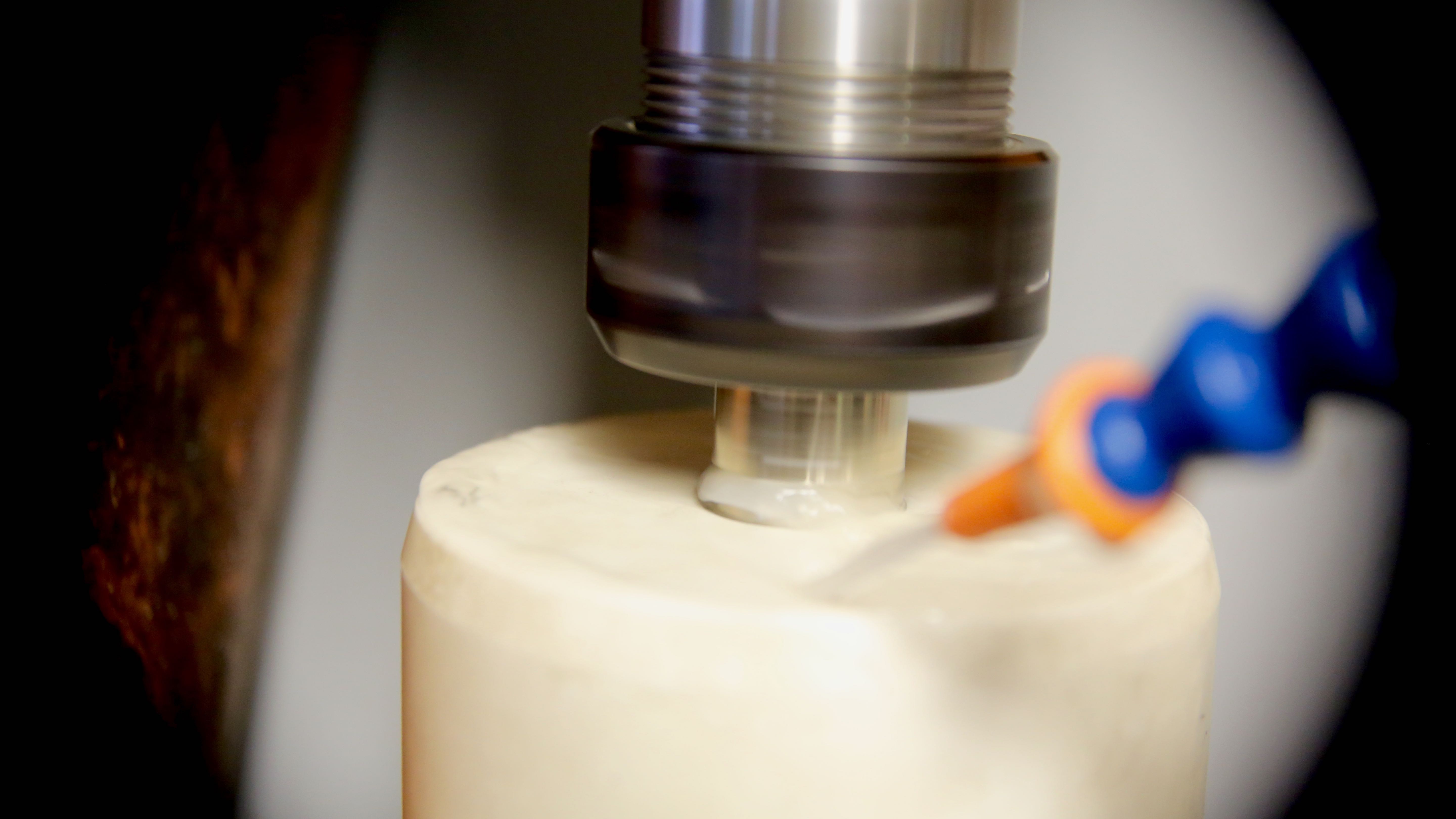
As eager as we are to get the nozzle glowing yellow; we took the time to put it in now. We are quite pleased with the outcome so far (to be tested of course). We wonder if aluminum and copper will be printable with this setup?!?
The main reason we bit the bullet now is the crucible assembly will be much more fragile after its all been fired, so we needed to do it now if it is to be done with our initial setup.
Stainless feels like cutting butter after all this alumina (high purity sapphire ceramic)!
Doh! Some more alumina to cut :/
Now it is open; now it is closed! Repeat. On retract g-code that is.
Water tight fit! Should hold glass 🙂
Nice and slim design – doesn’t take much from the very precious under nozzle clearance
This will connect to a stepper driven rack and pinion. To be continued.
Today was a big day for the 3D printer! The machining for our lovely new crucible is now complete.
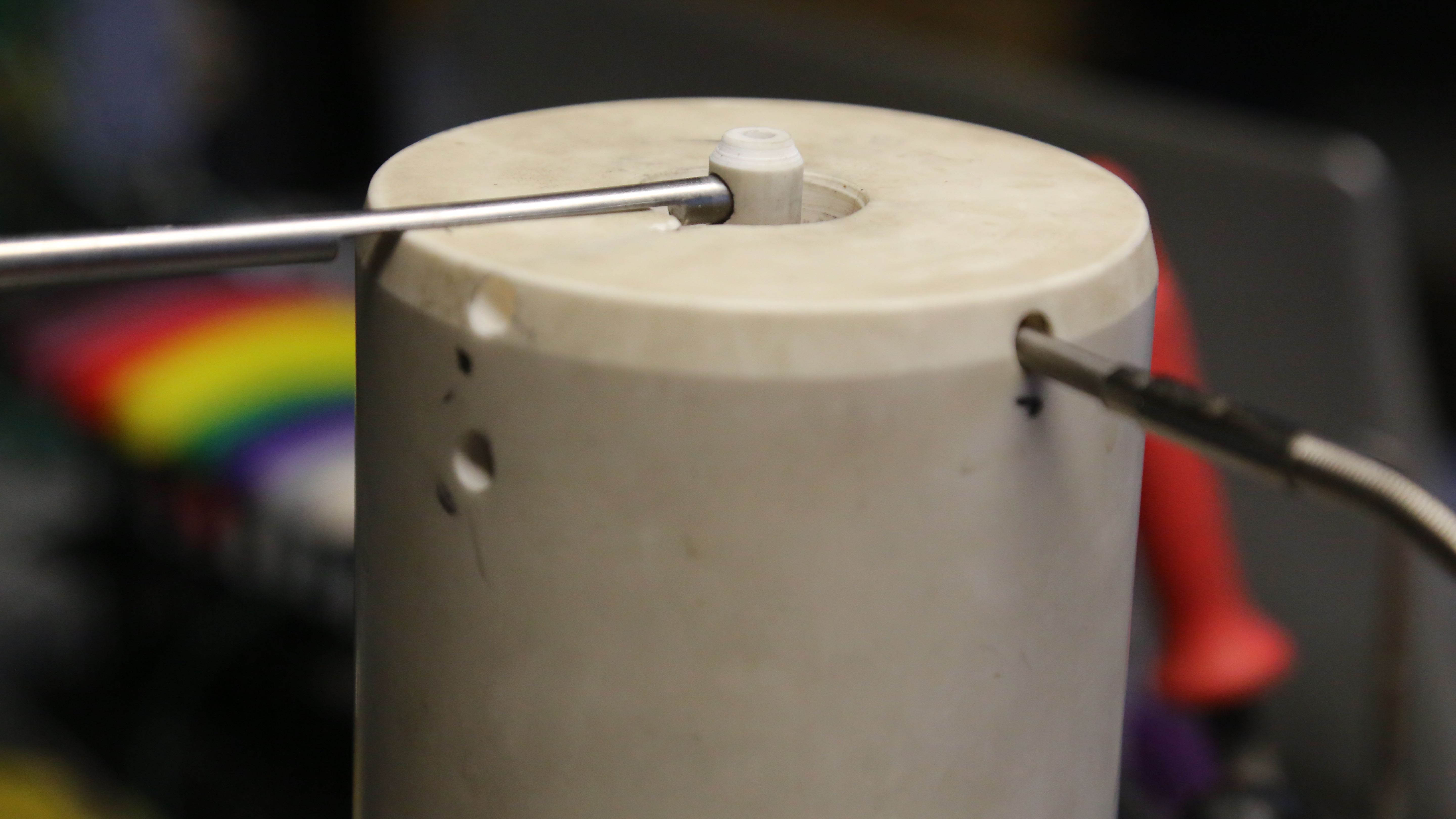
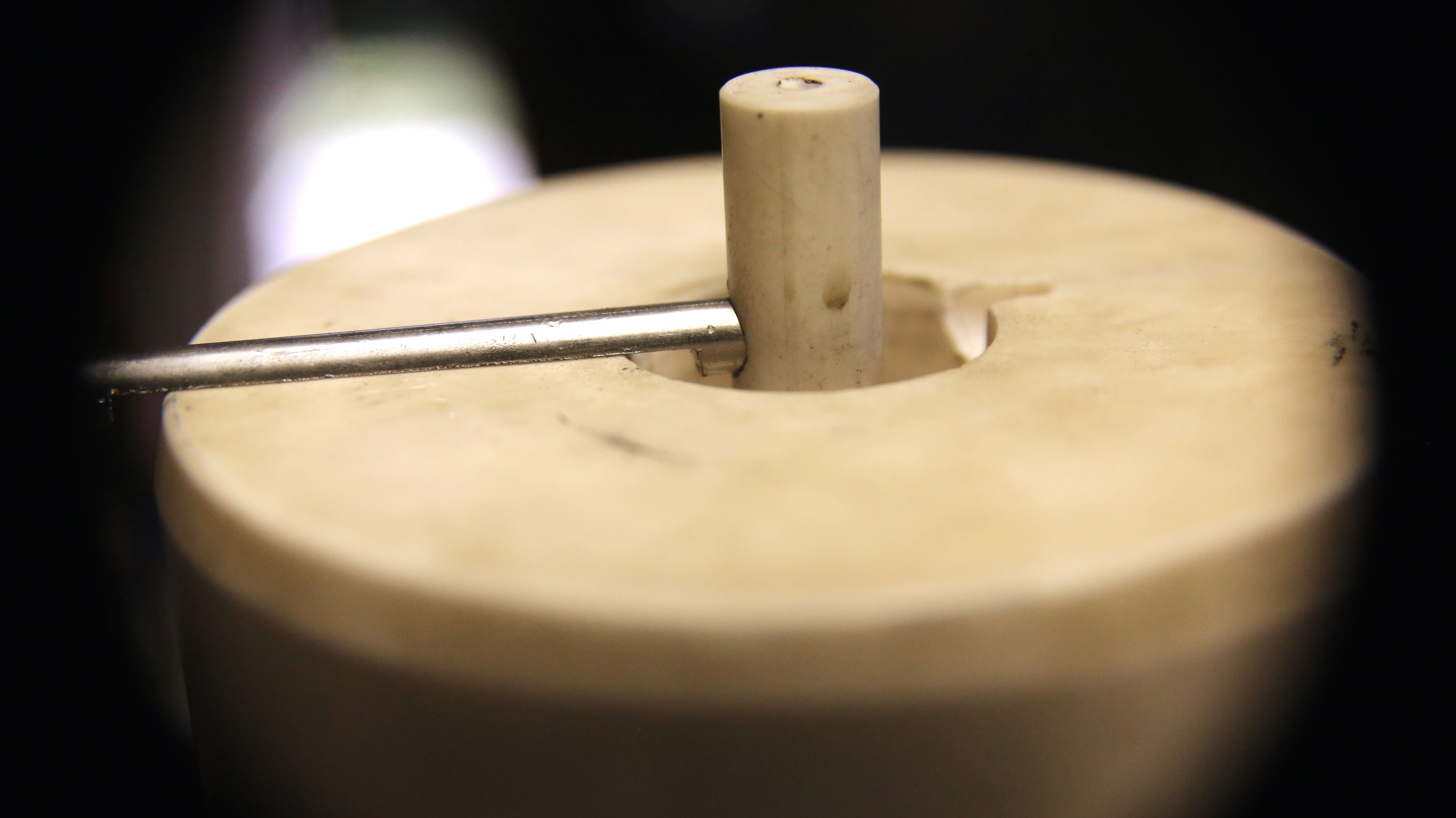
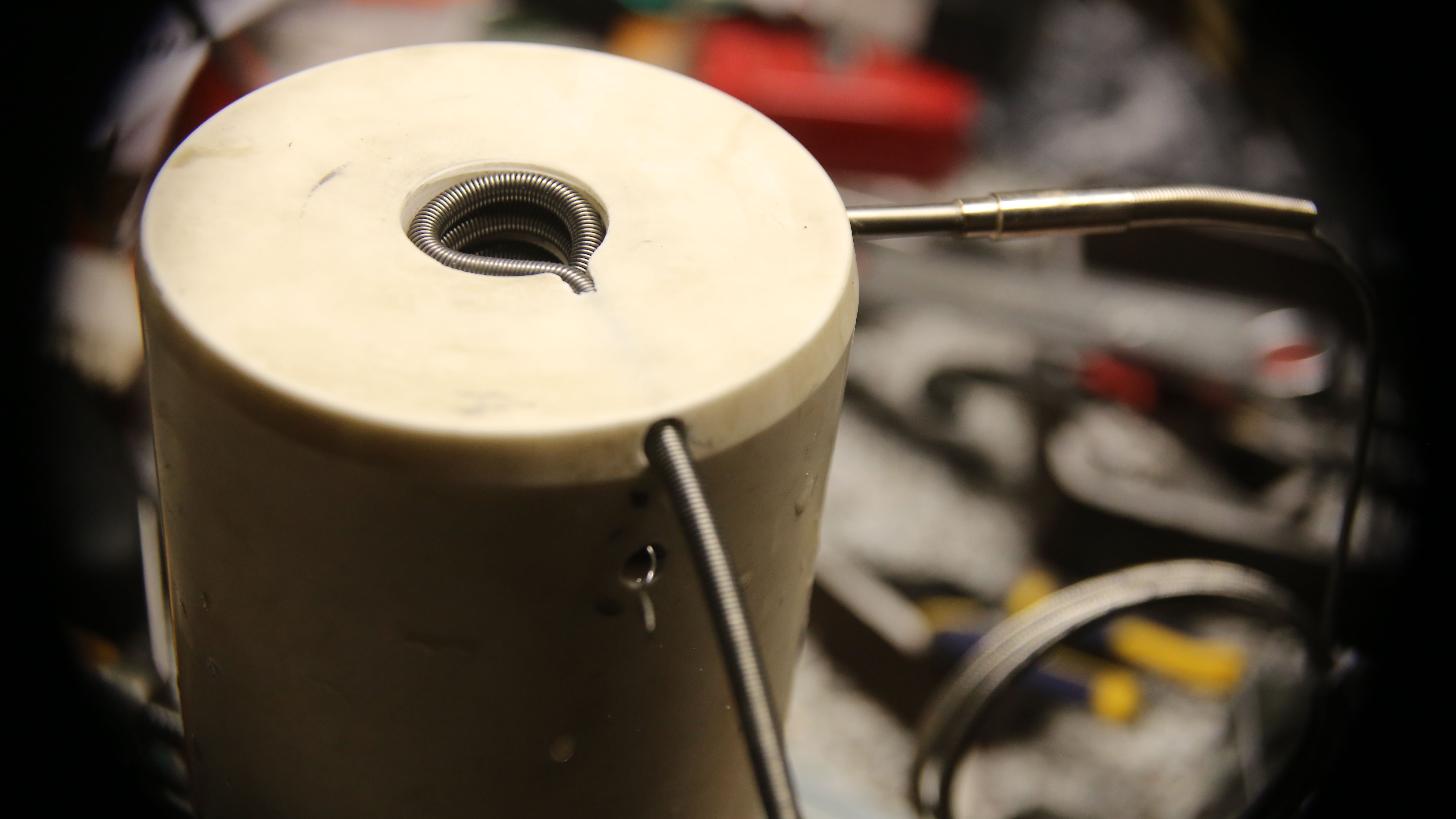
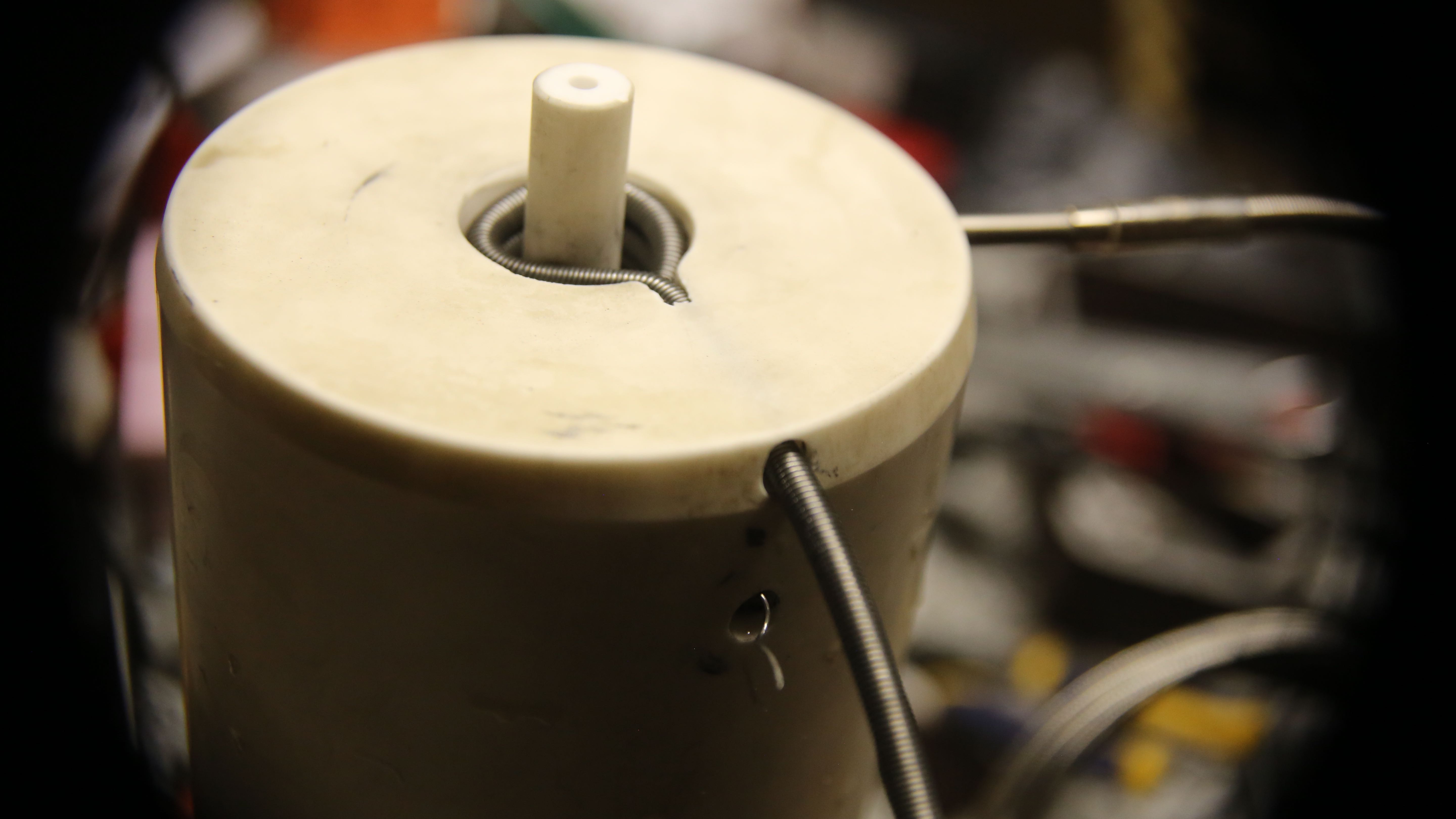
Shown here is a test fitting of the nozzle coil at last!
Not to fear; it will get pulled to spec and properly spaced before we will it with 3000F refractory. In fact, that will be the next entry as far as the crucible goes at least.
Then – we will be all set for the first firing! Whoooo-hoo!
Coil test fit without nozzleThe probe on right side back is the thermocouple and nozzle heater coil entry and exit are near center foreground
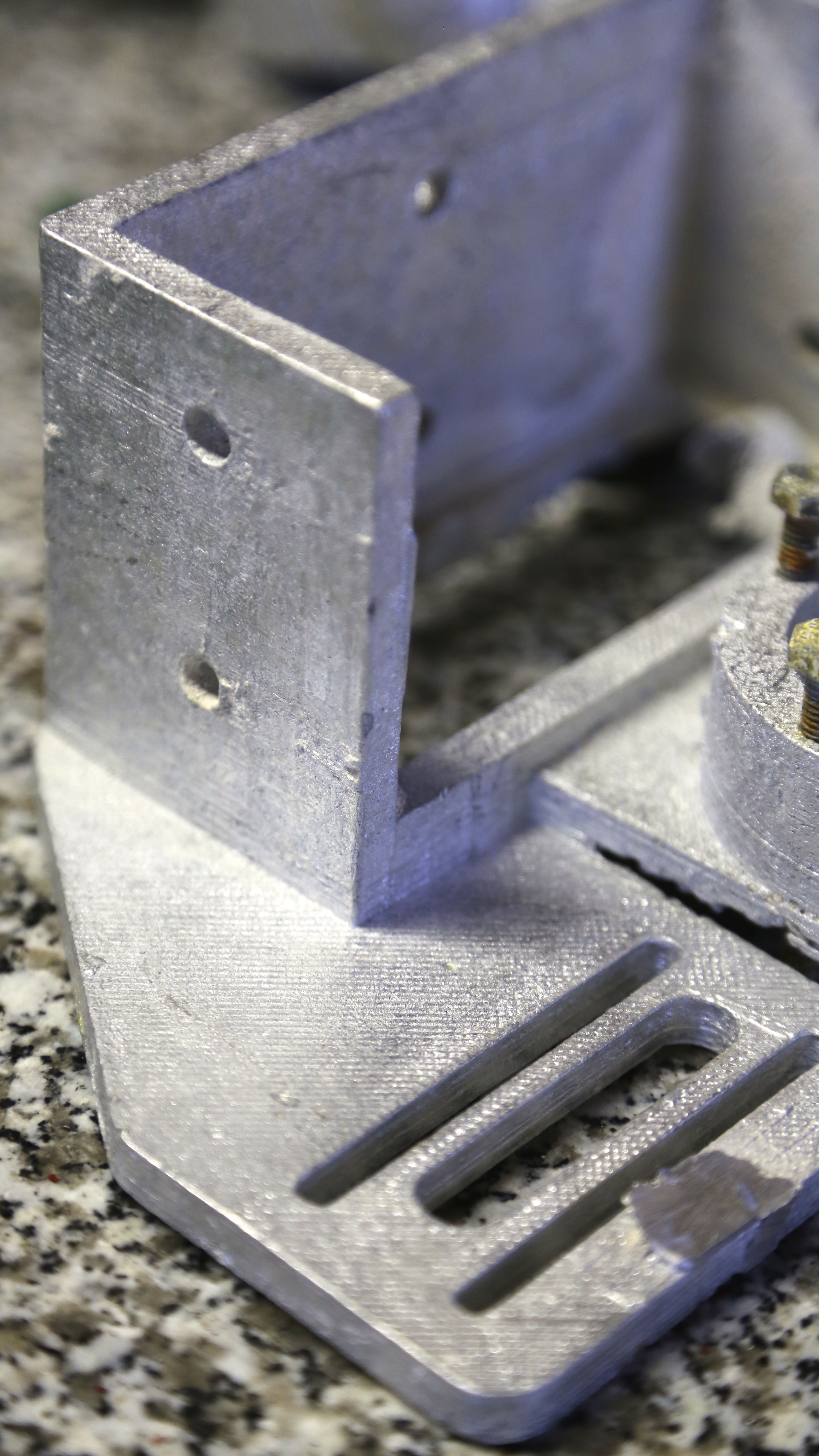
When we need a custom part around here, often we will print it out of plastic and then perform our lost PLA process to the print transforming it into a flawless metal copy.
Cast directly from 3D print, with no machining (other than vent cut off)
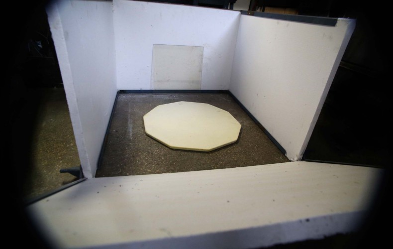
The frame is about complete now with working (drop down) front door. You can see our 14″ ceramic window to be installed in our door.
The build platform is a 21″ kiln shelf that MIT’s Glass Lab suggests that glass will stick nicely at print chamber temperatures (800F) and pop off when cools. We can’t wait for that!
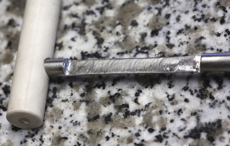
We got most the machining of the crucible done now. We just need to poke 3 small holes in the sides of it and we are done machining the very hard Alumina!
That said we have to wait for the bits to arrive – should be tomorrow. Then we can put the heater coils in and test fire it pretty soon after.
Let the glass flow, let it flow!
Note the nozzle currently protrudes too far – it will get cut in the near future.
The rest of our printer is currently sitting around waiting for this super hot end and we can’t wait to let it have it.
We had some much needed steel arrive today. The bands around the crucible will be filled with mostly insulating refractory and some steel to connect and drive her ’round and ’round.