Blog : Initial Construction

SiC Heater Rod Rewire

SiC Heater Rod Rewire

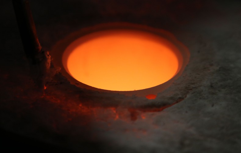
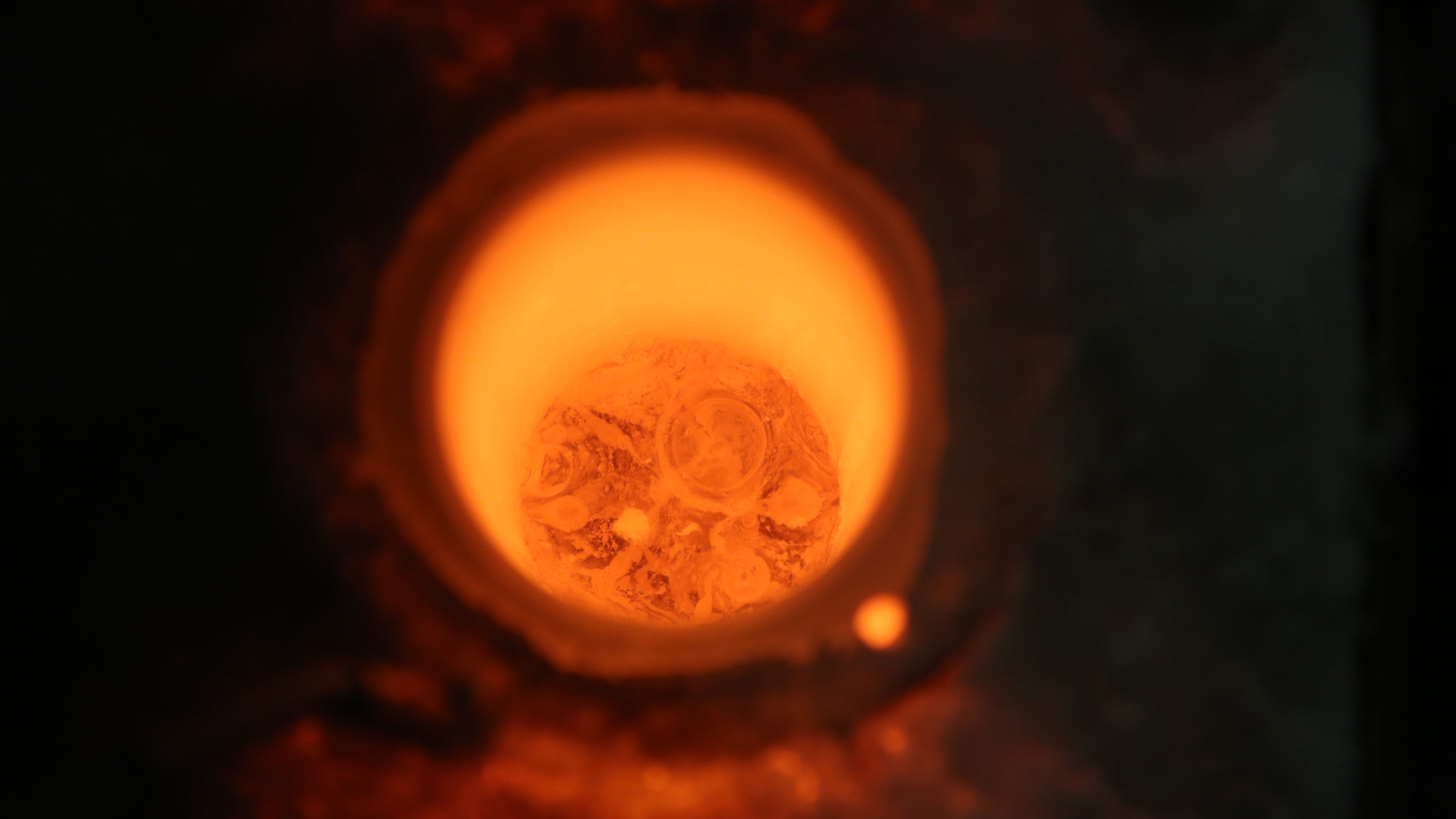
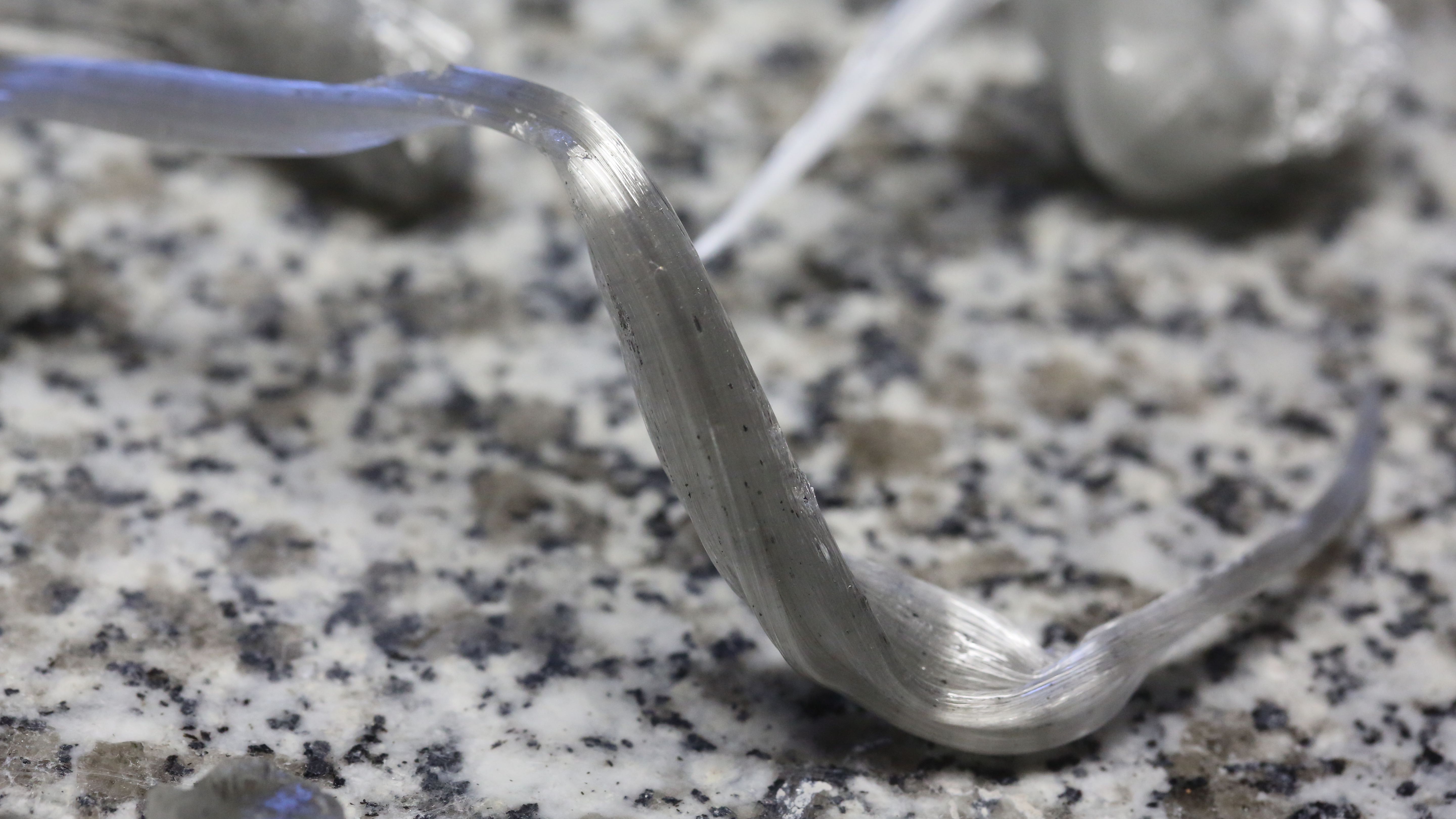
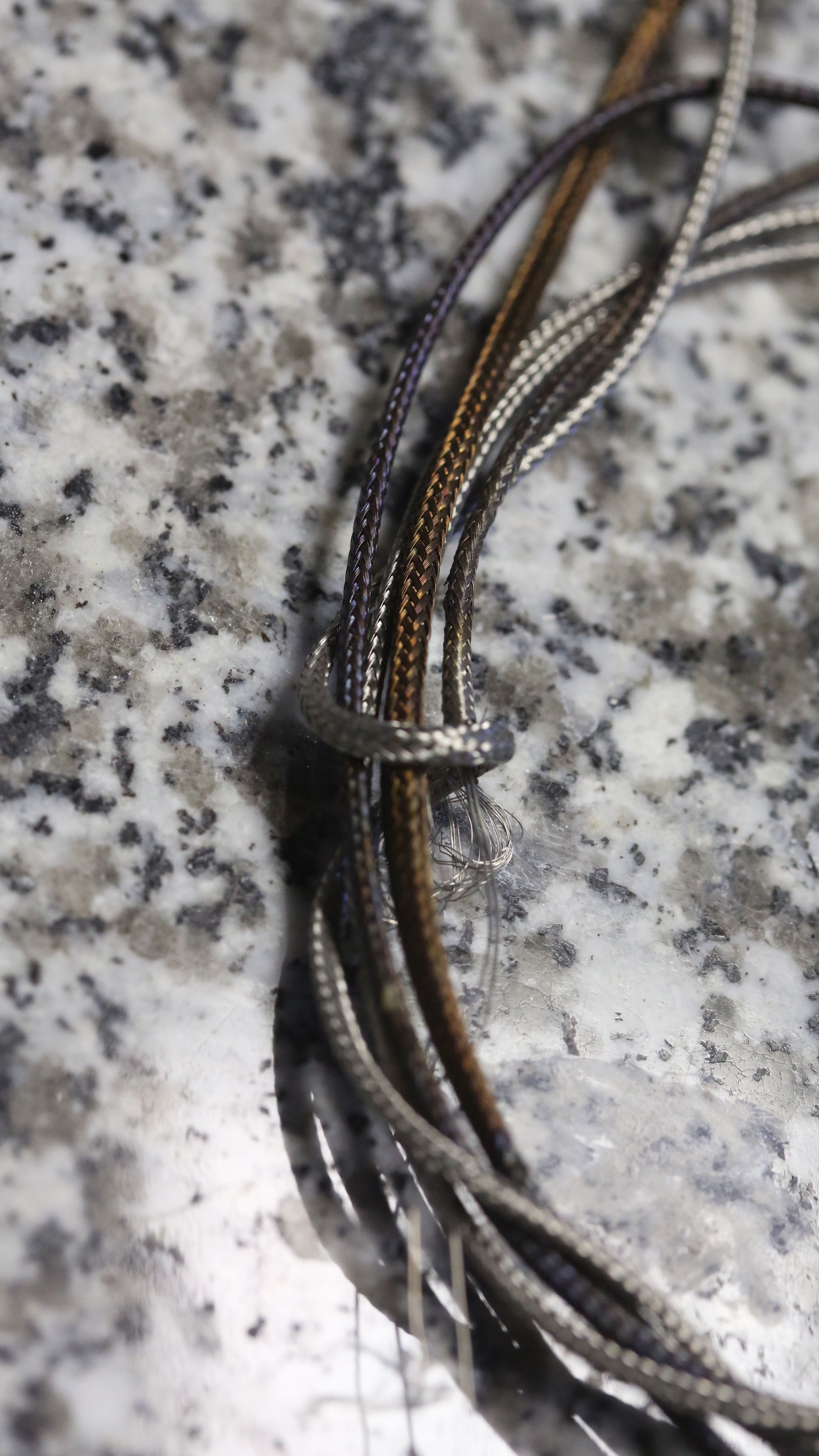
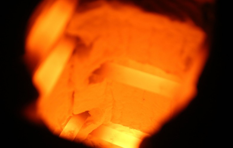
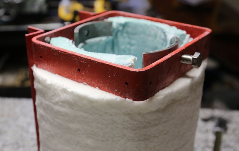
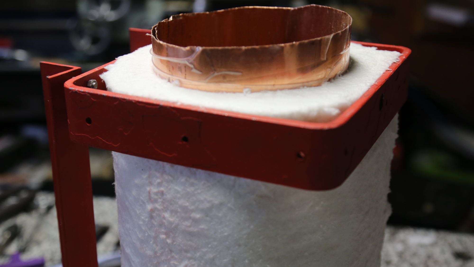
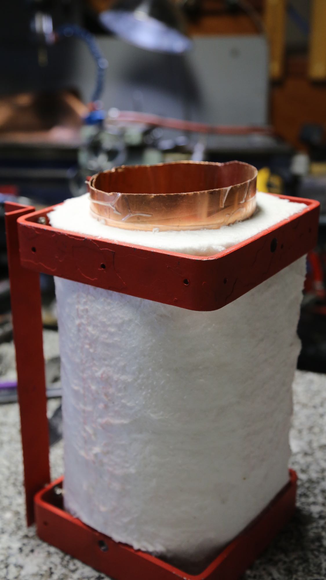
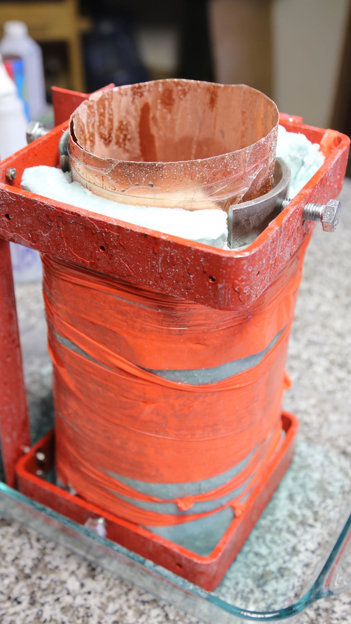
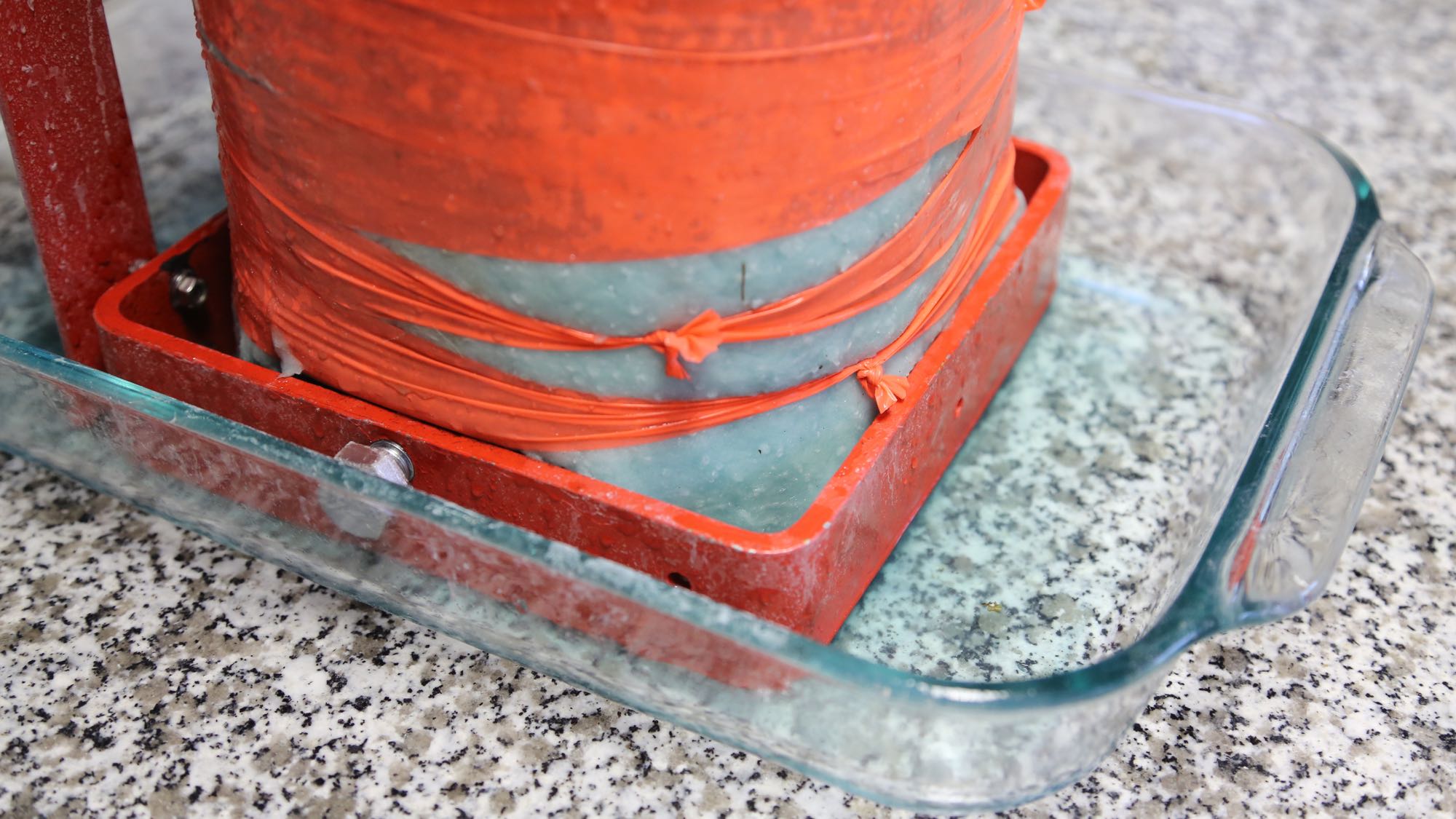
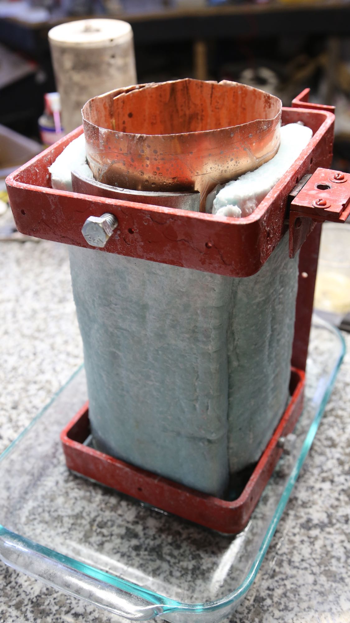
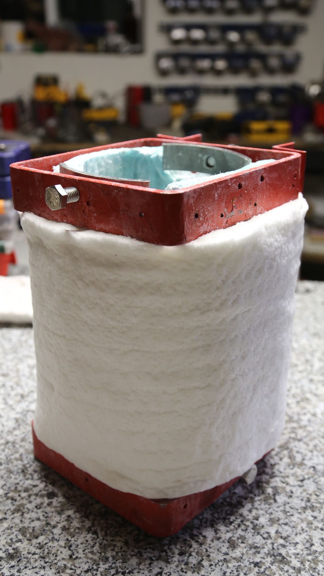
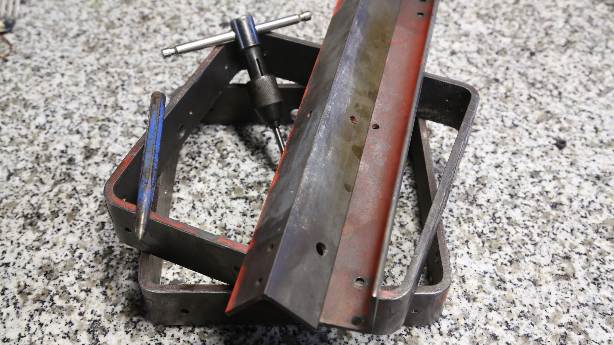
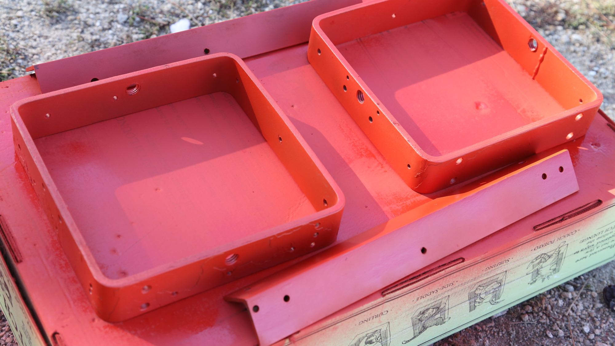
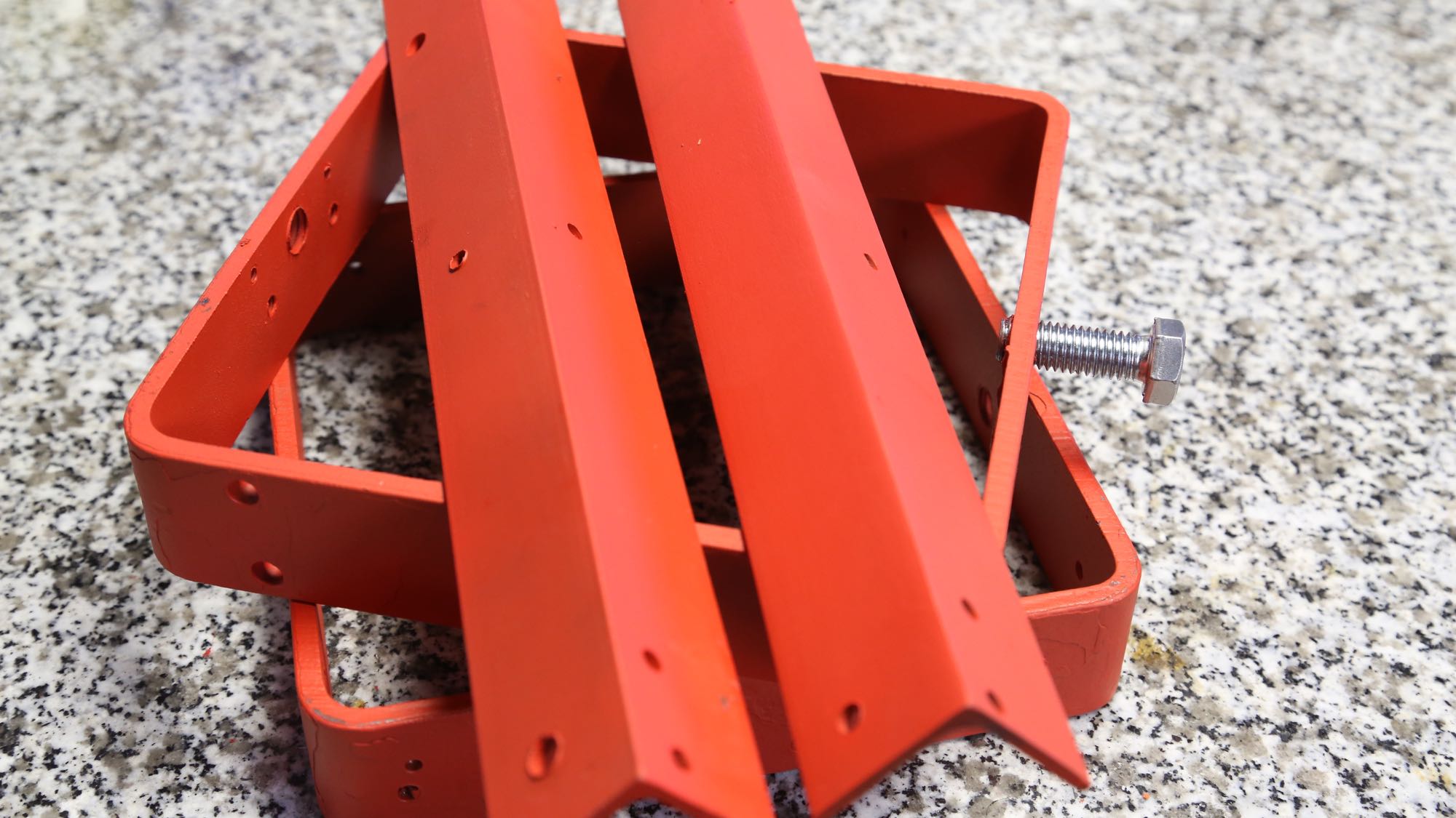
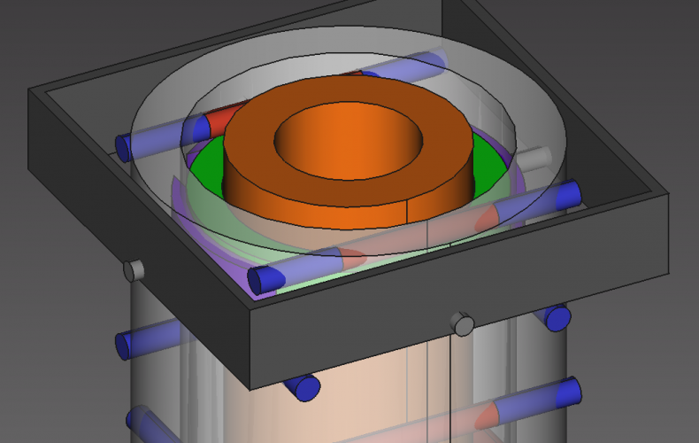
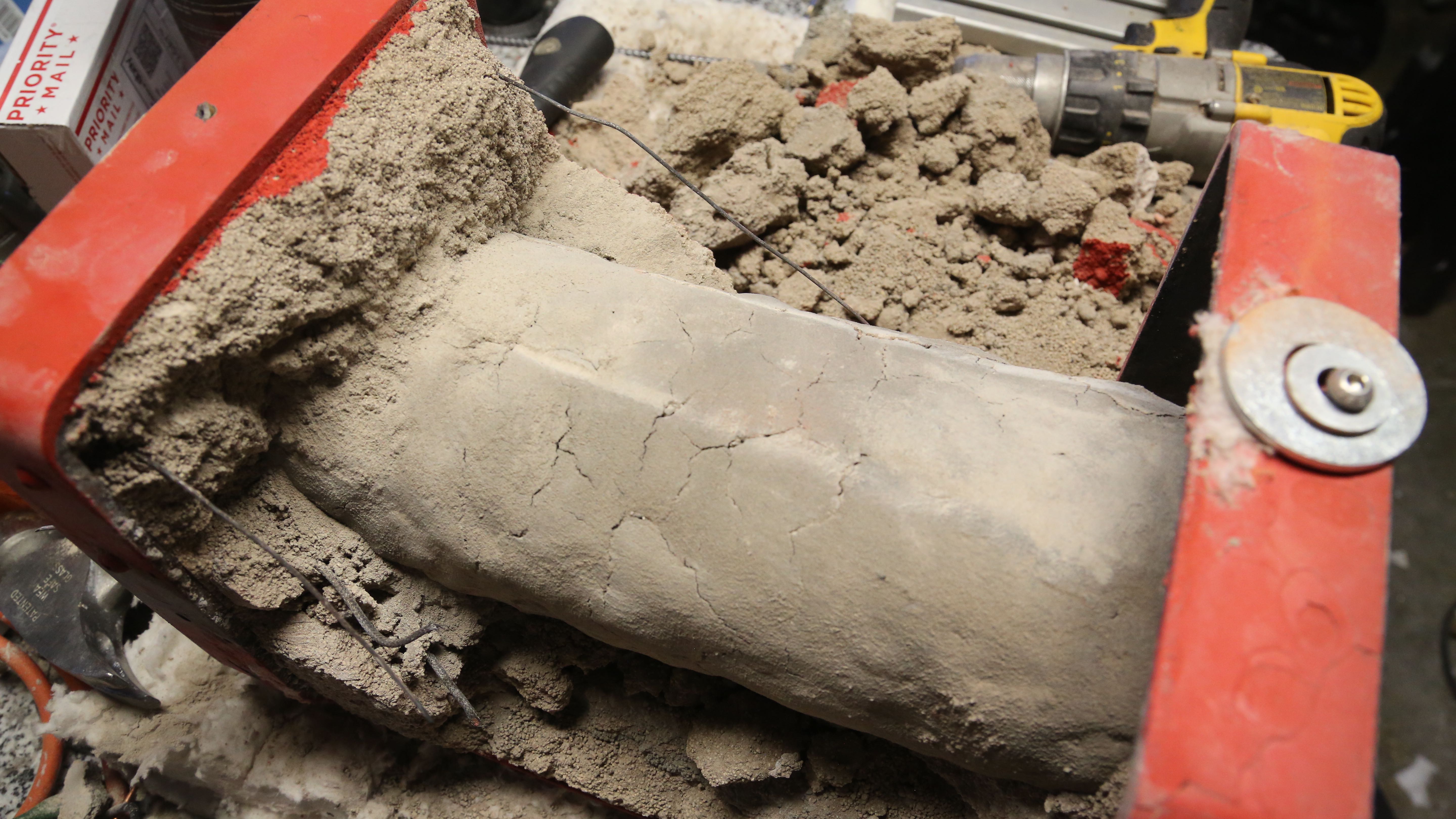
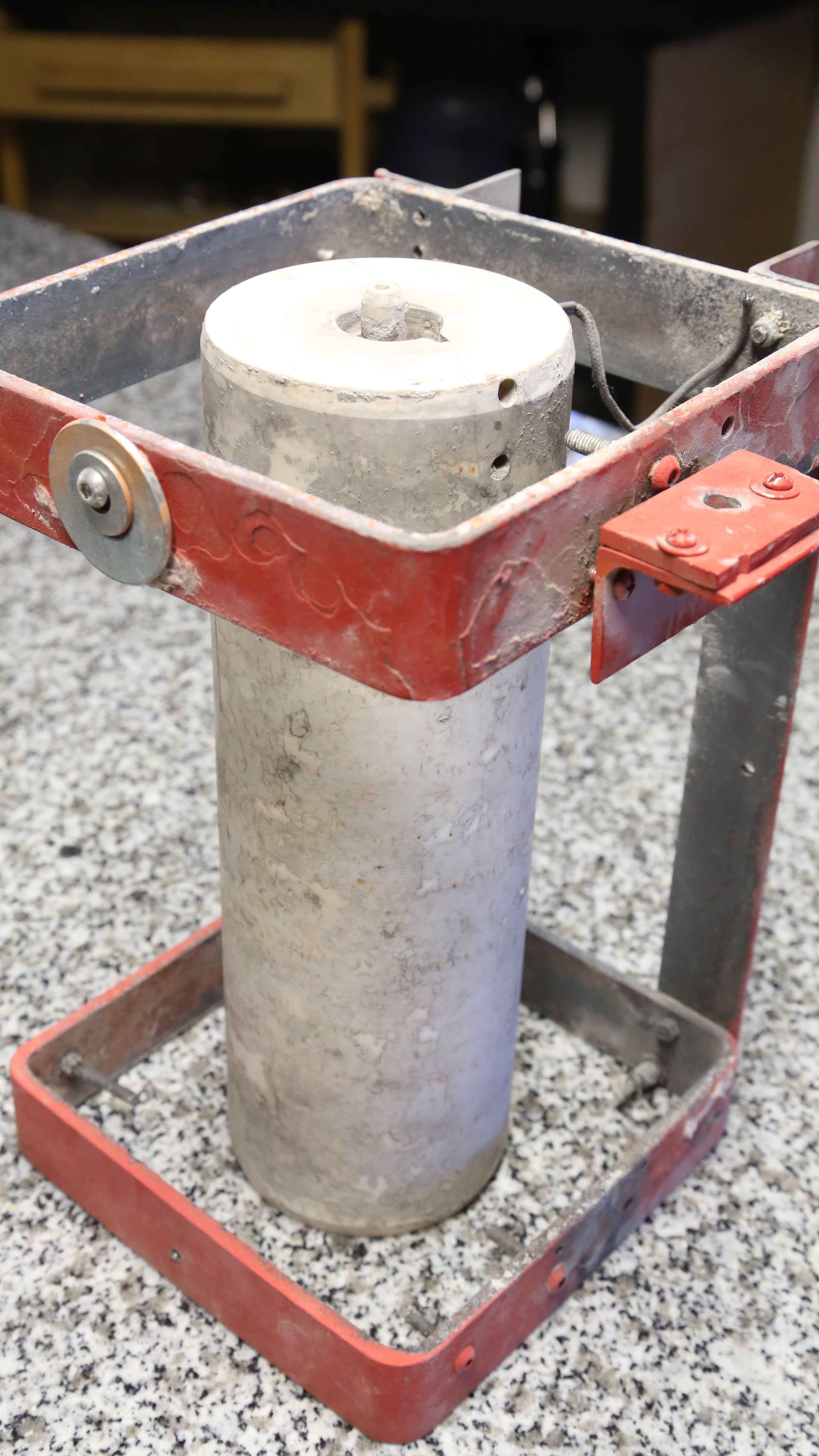
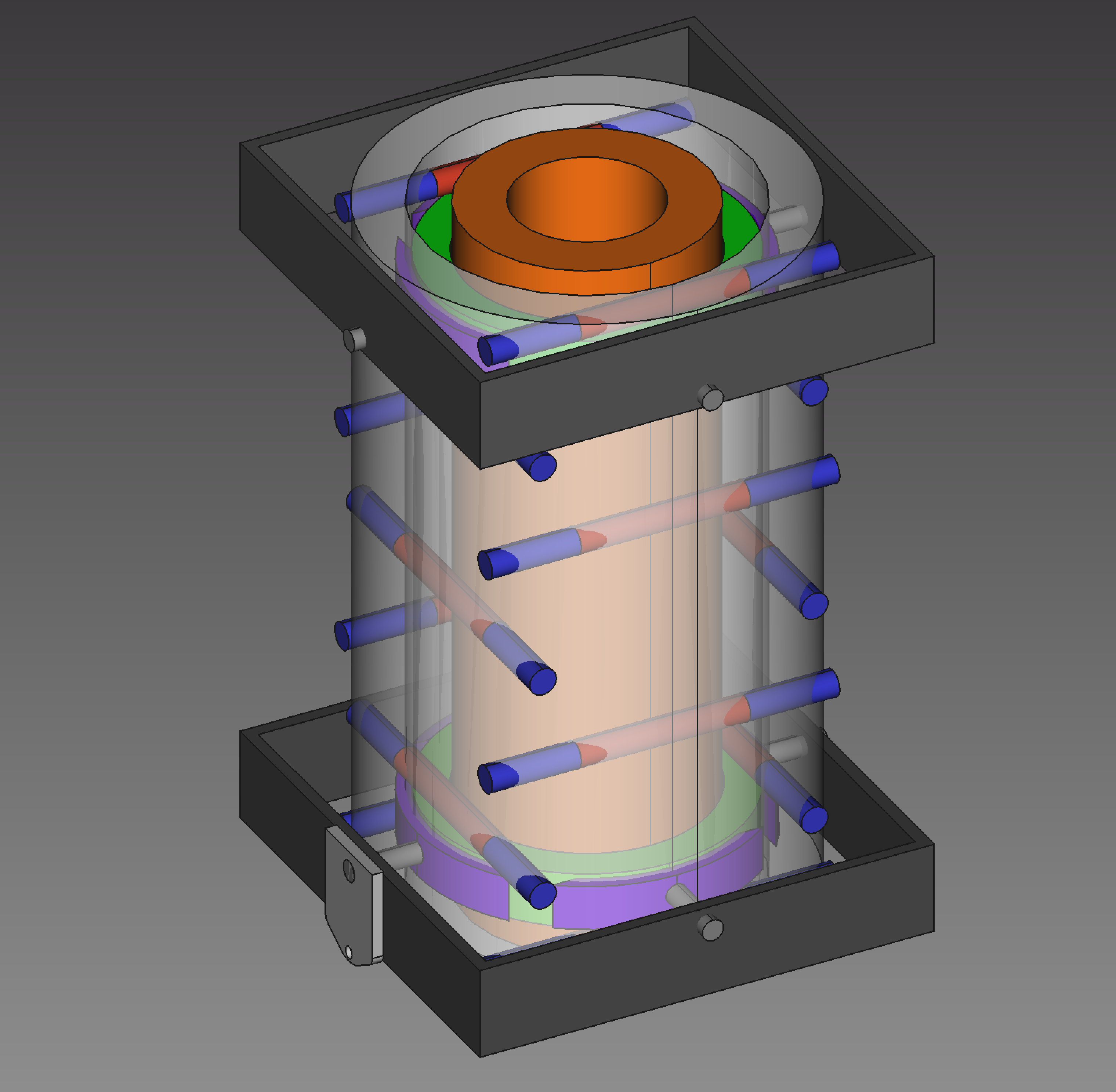
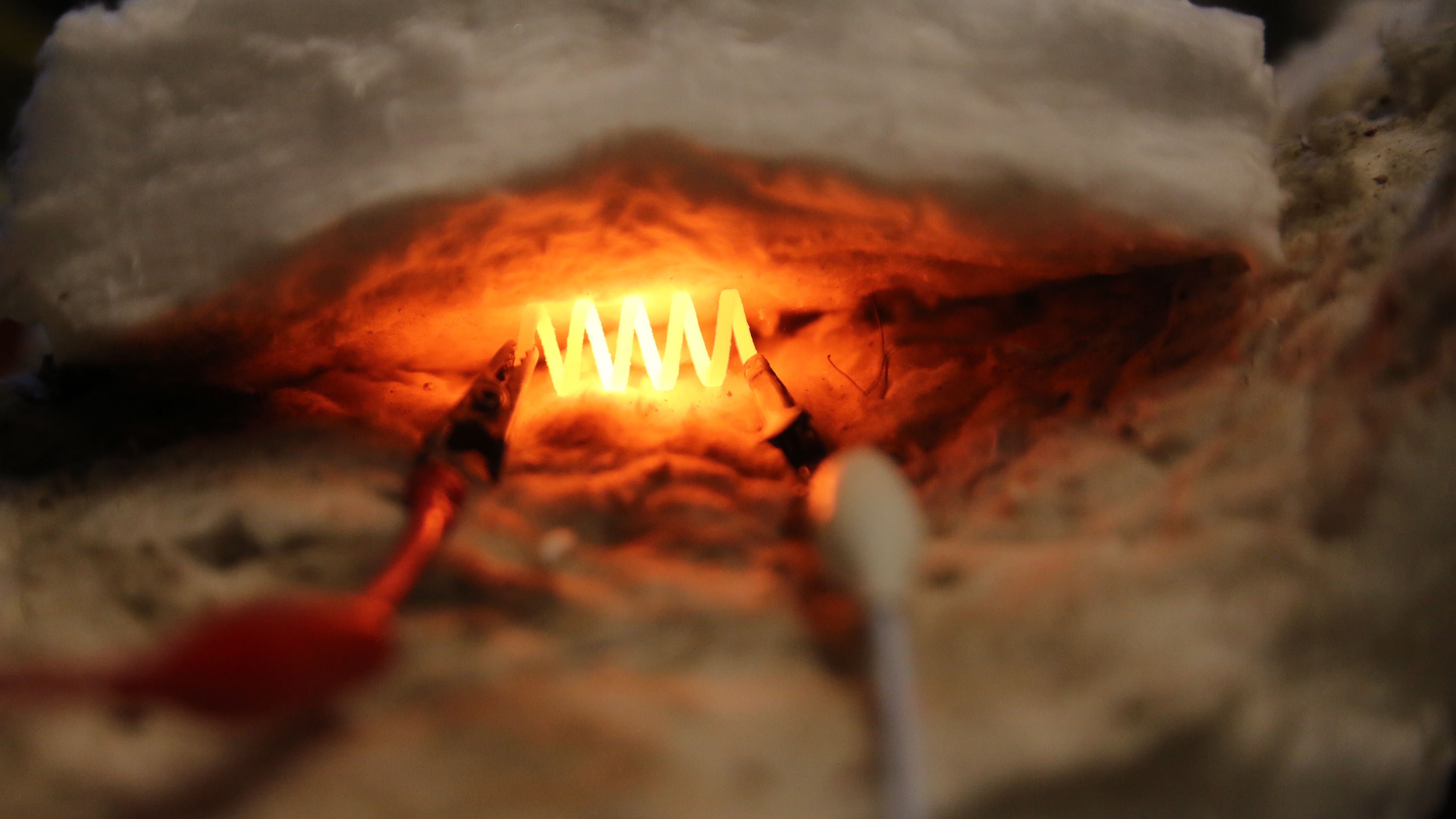
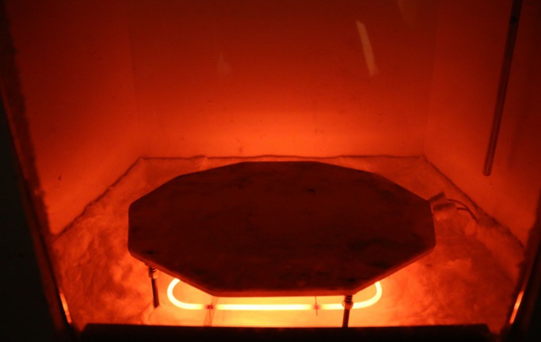
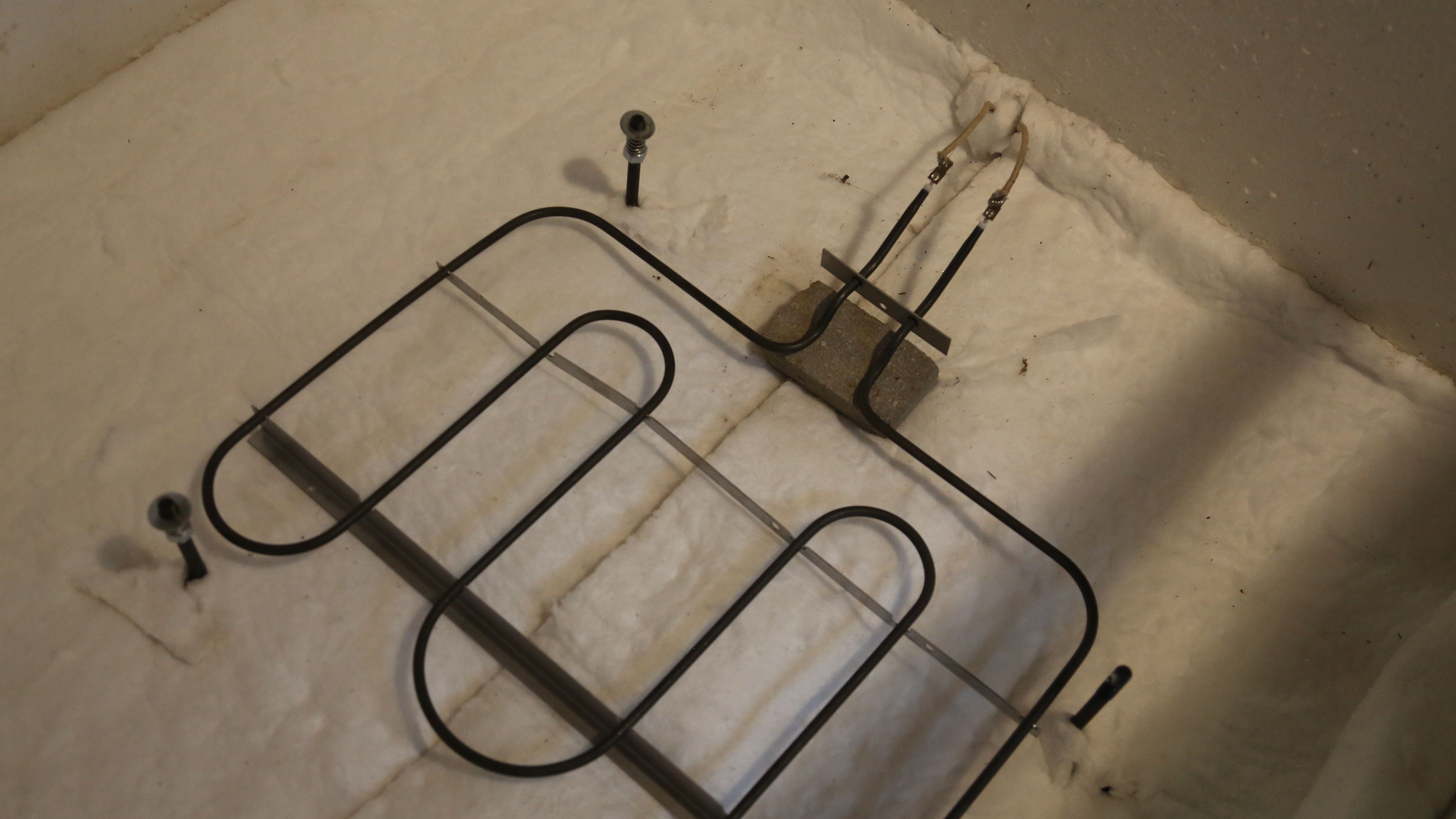
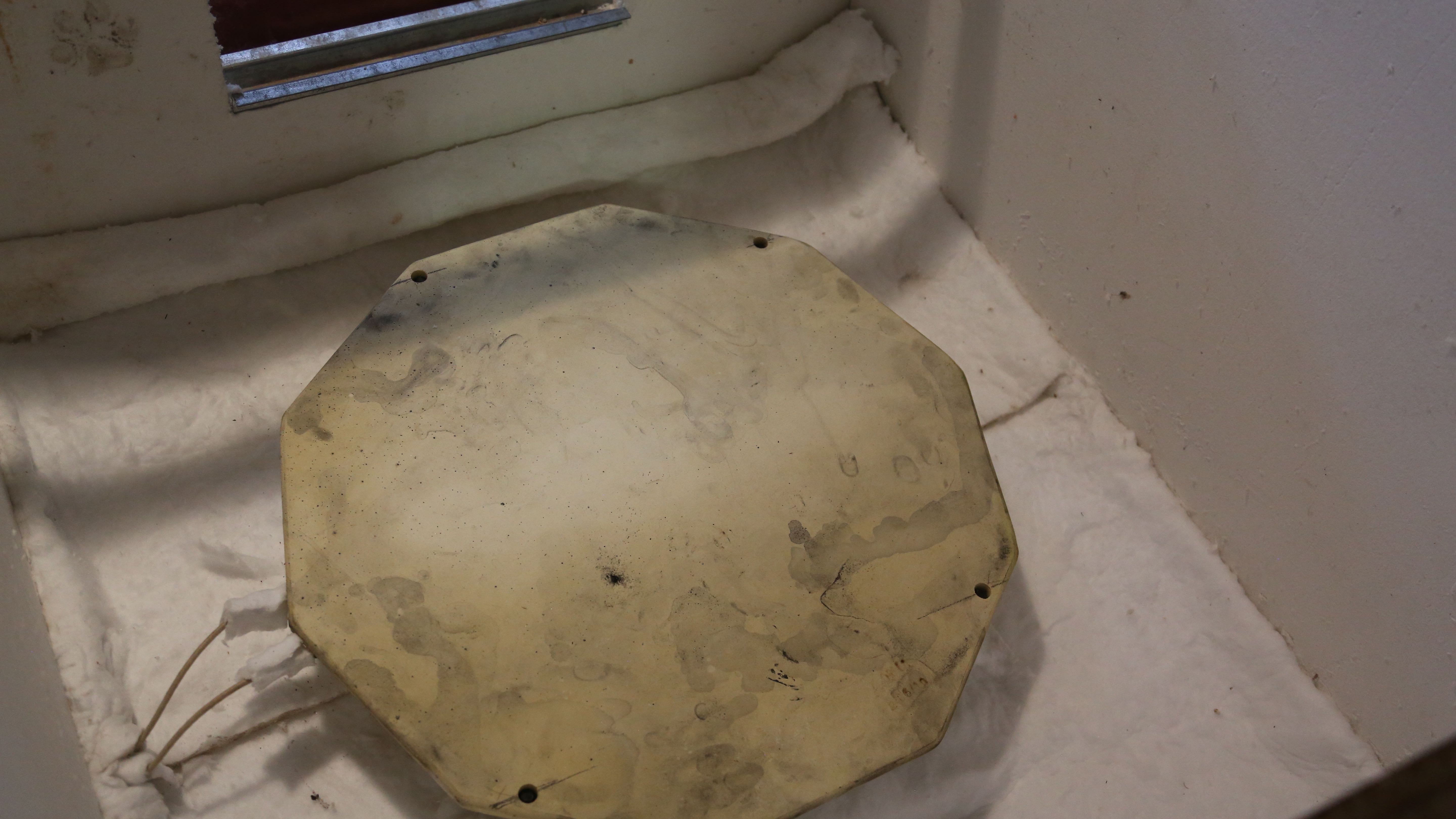
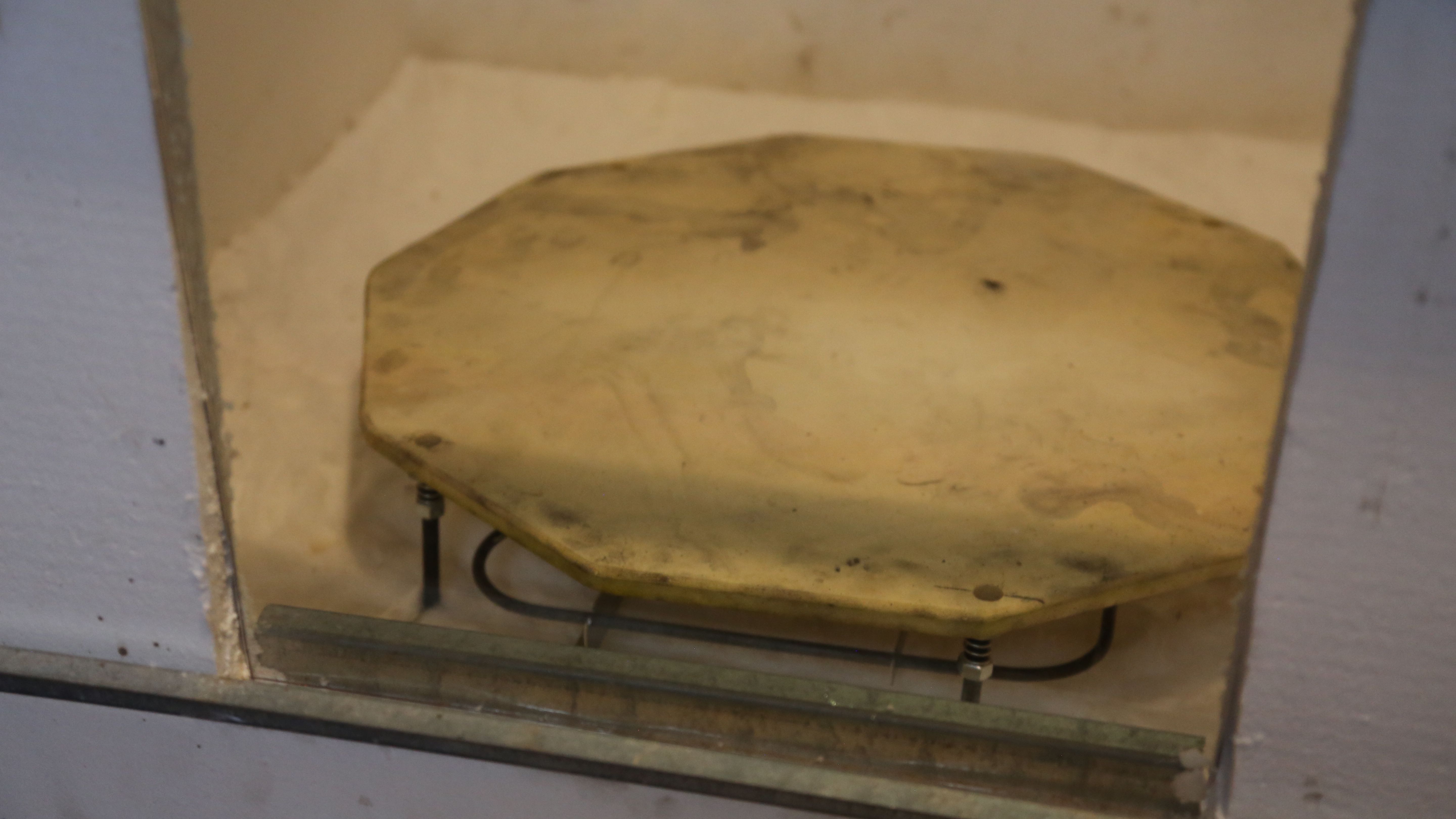
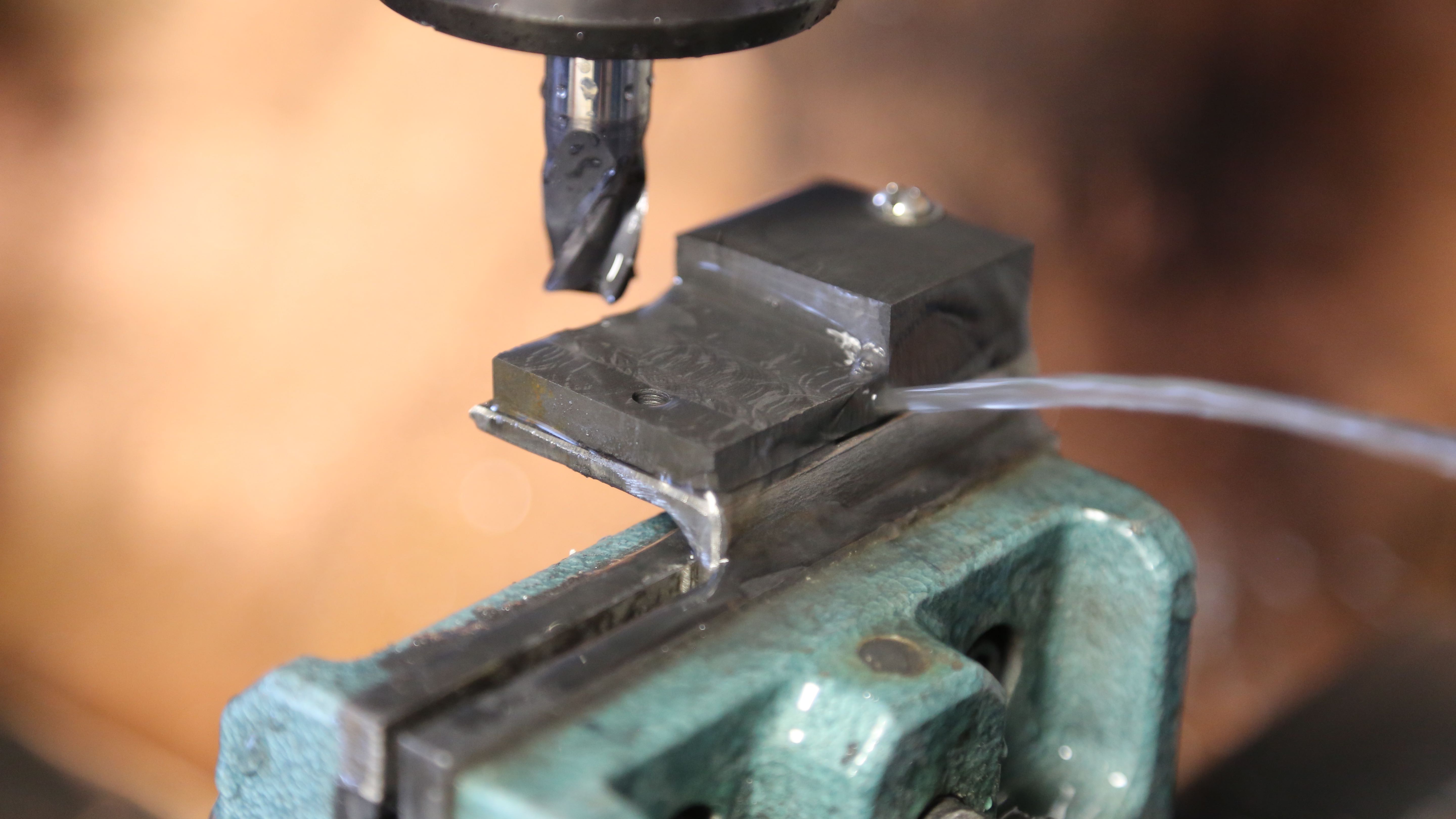
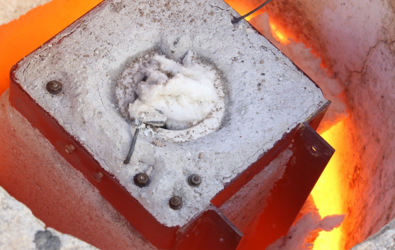
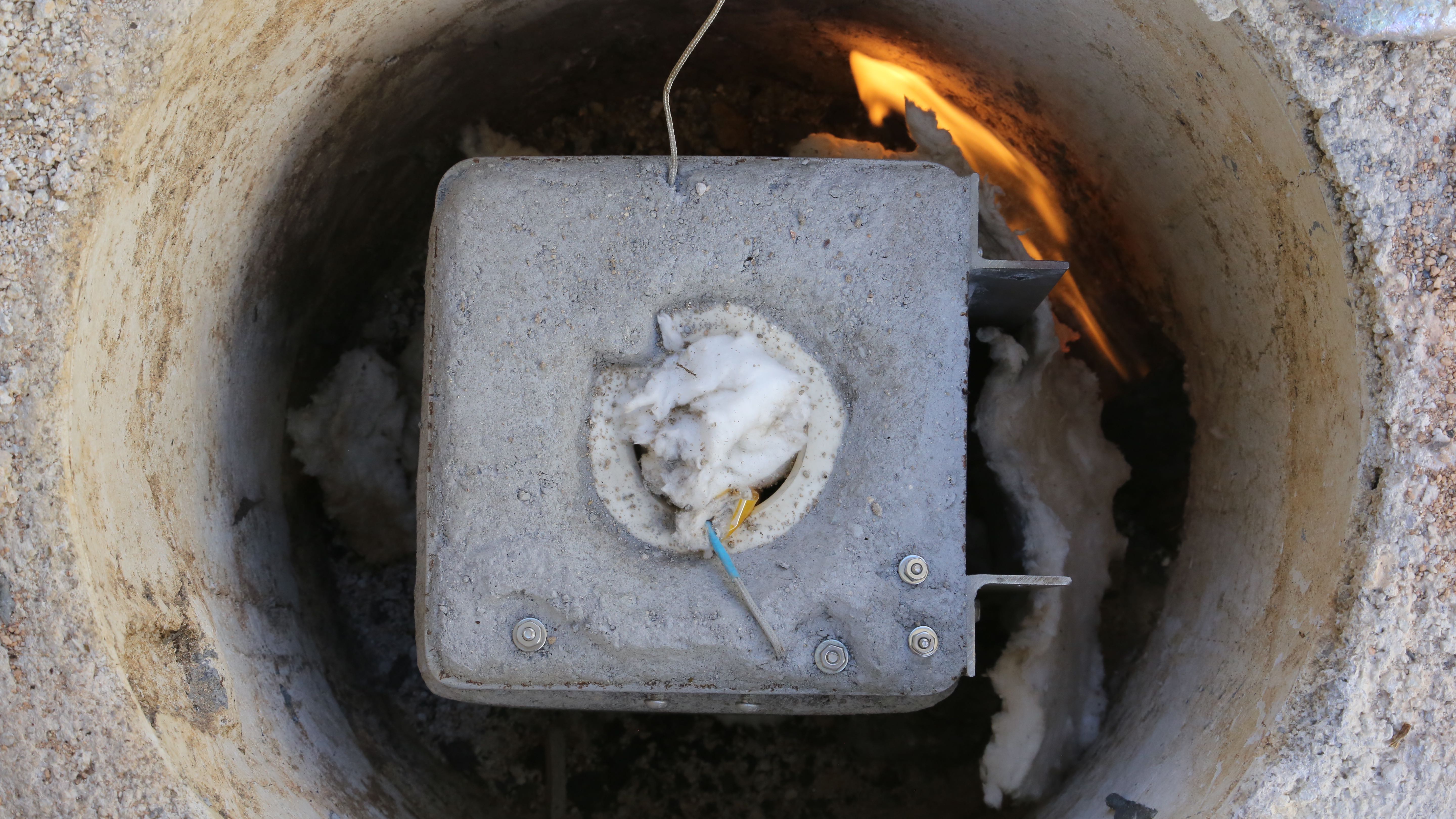
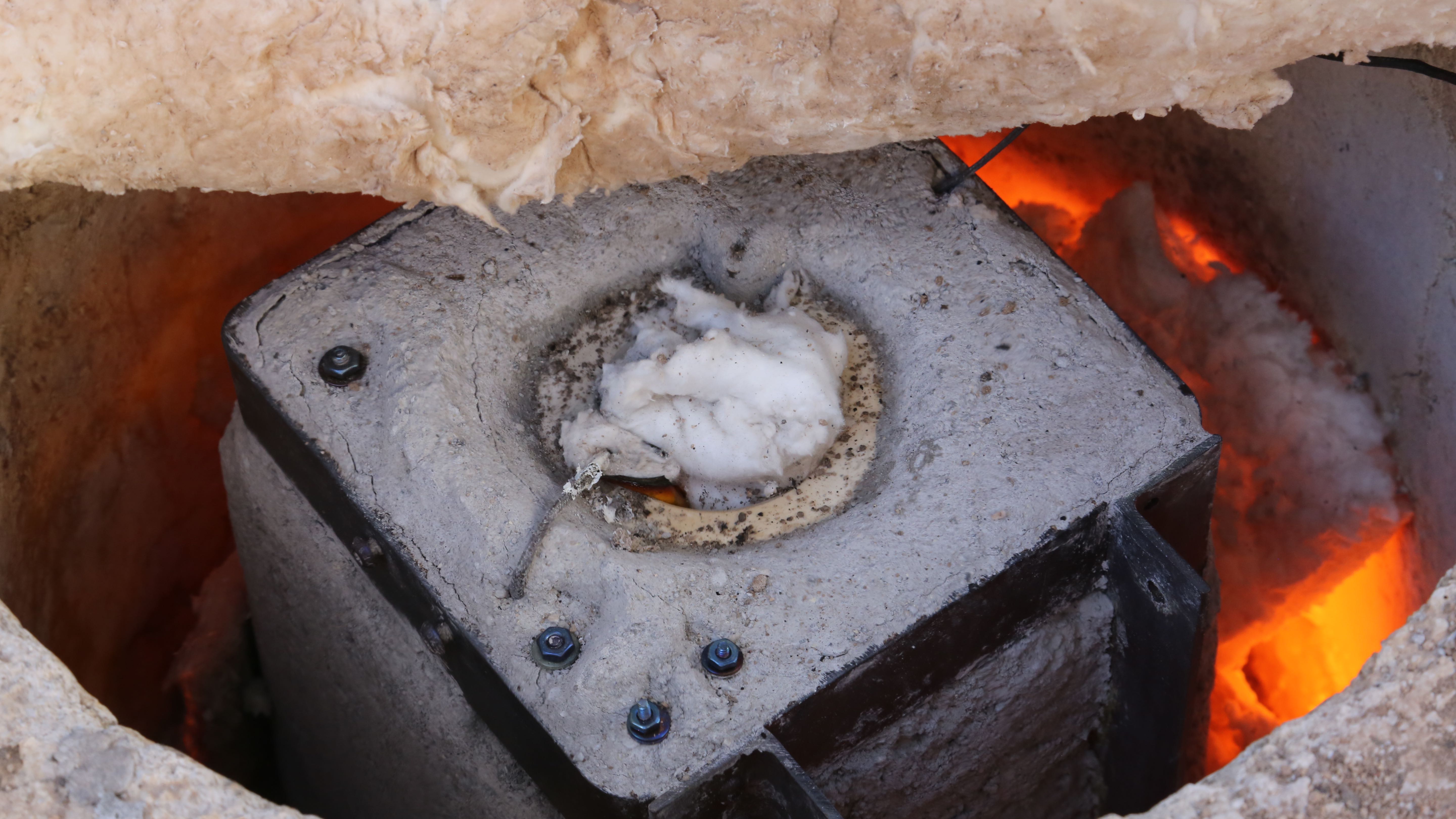
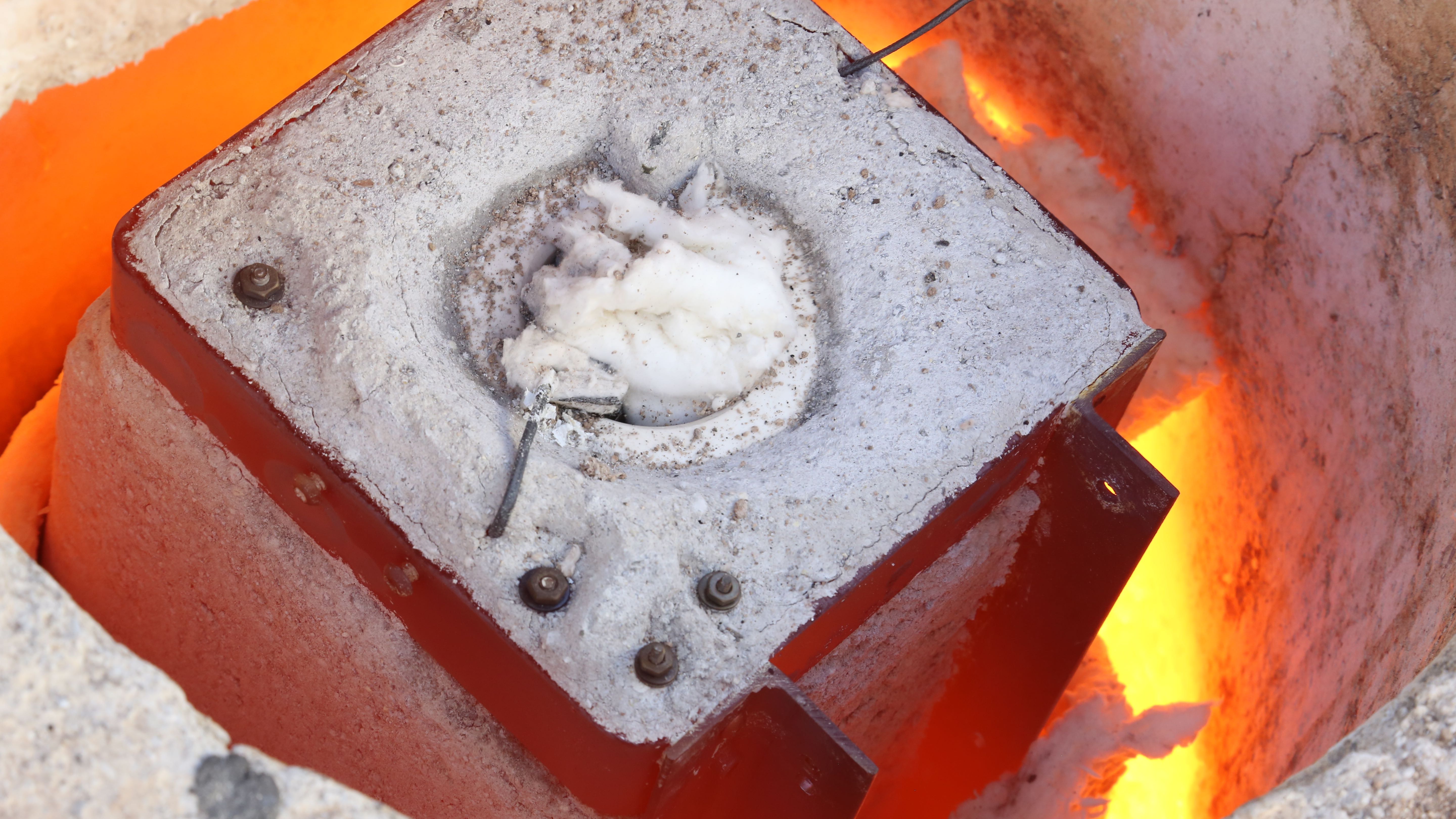
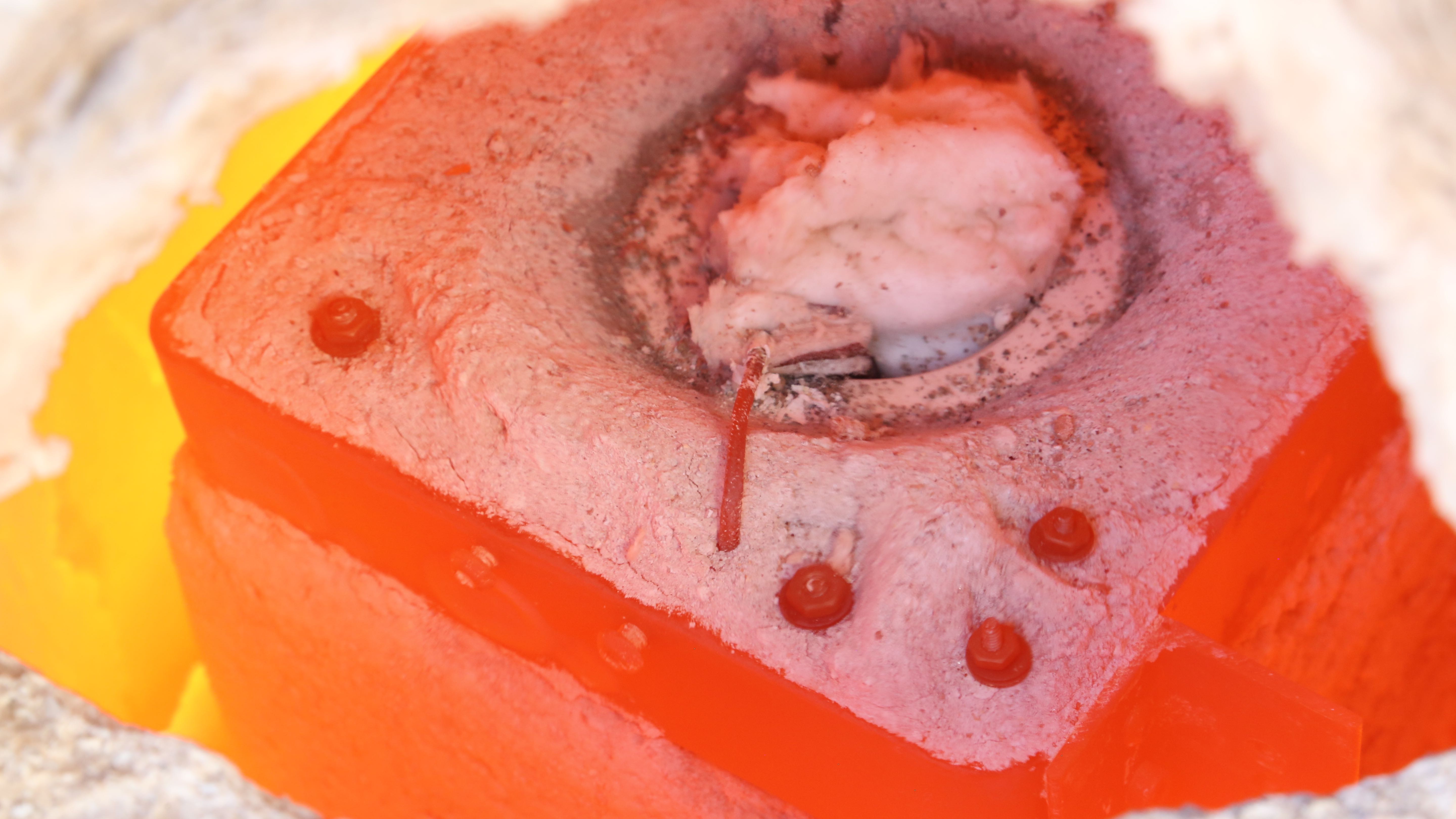
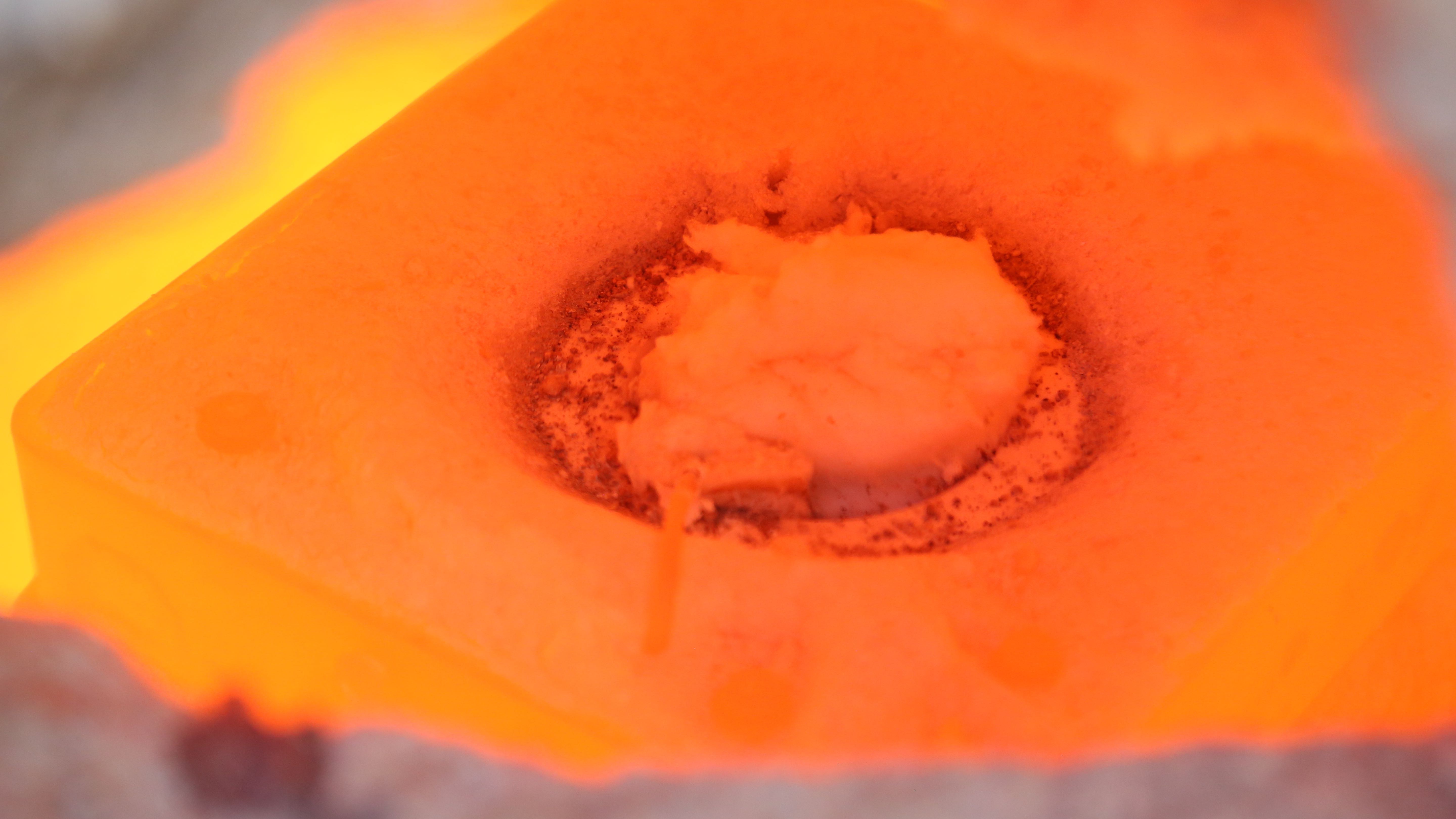
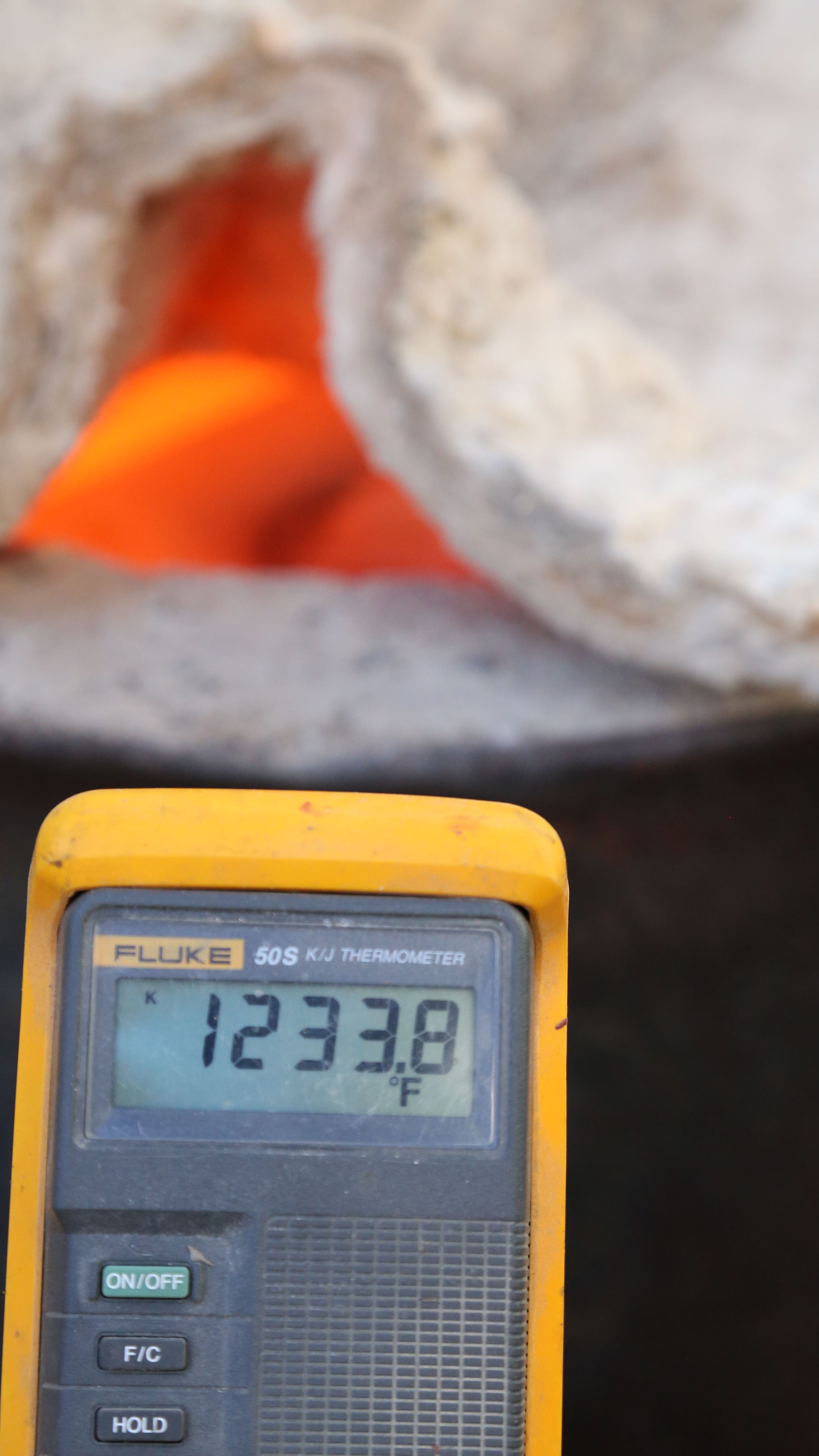
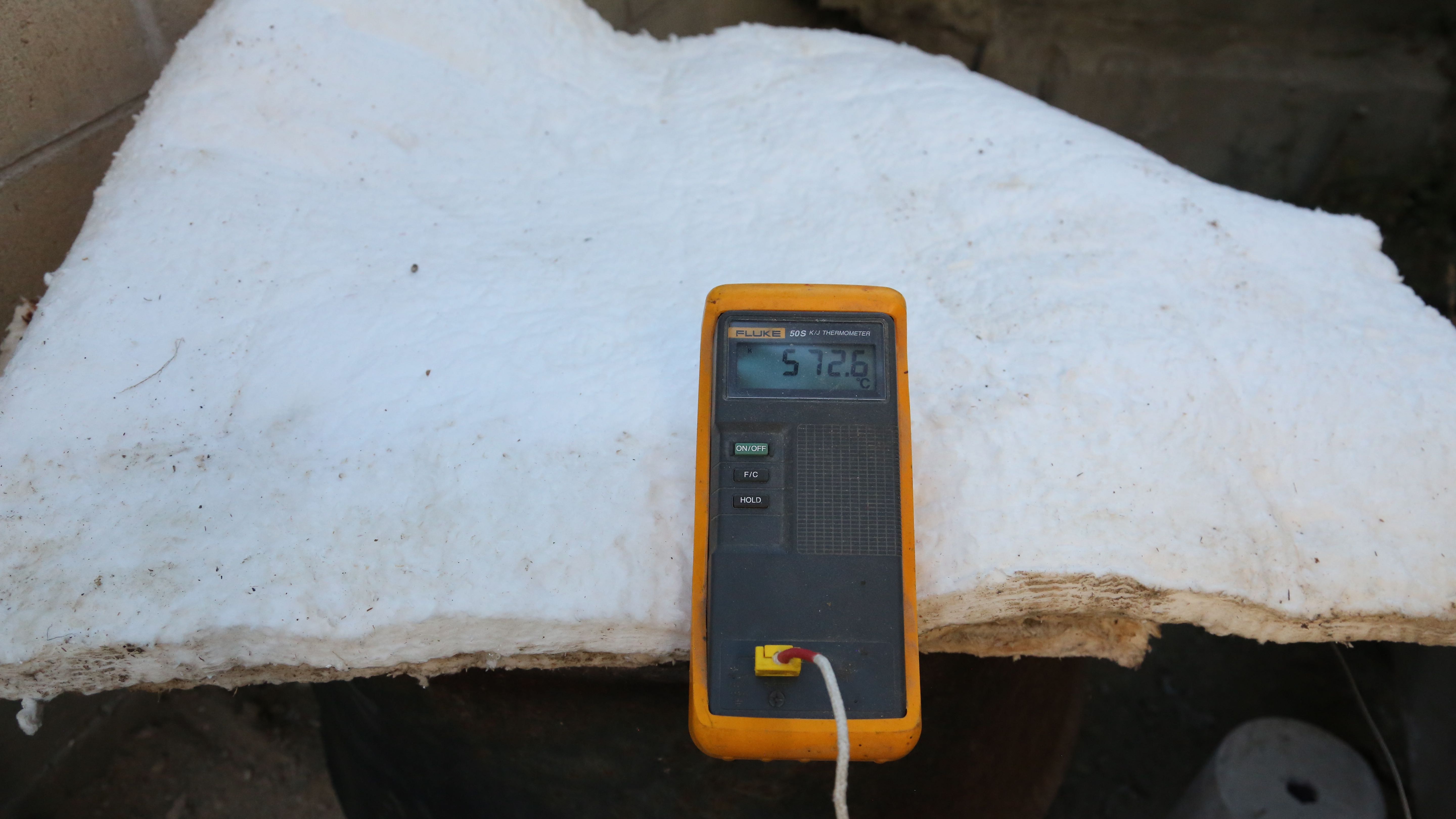
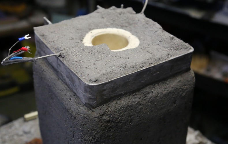
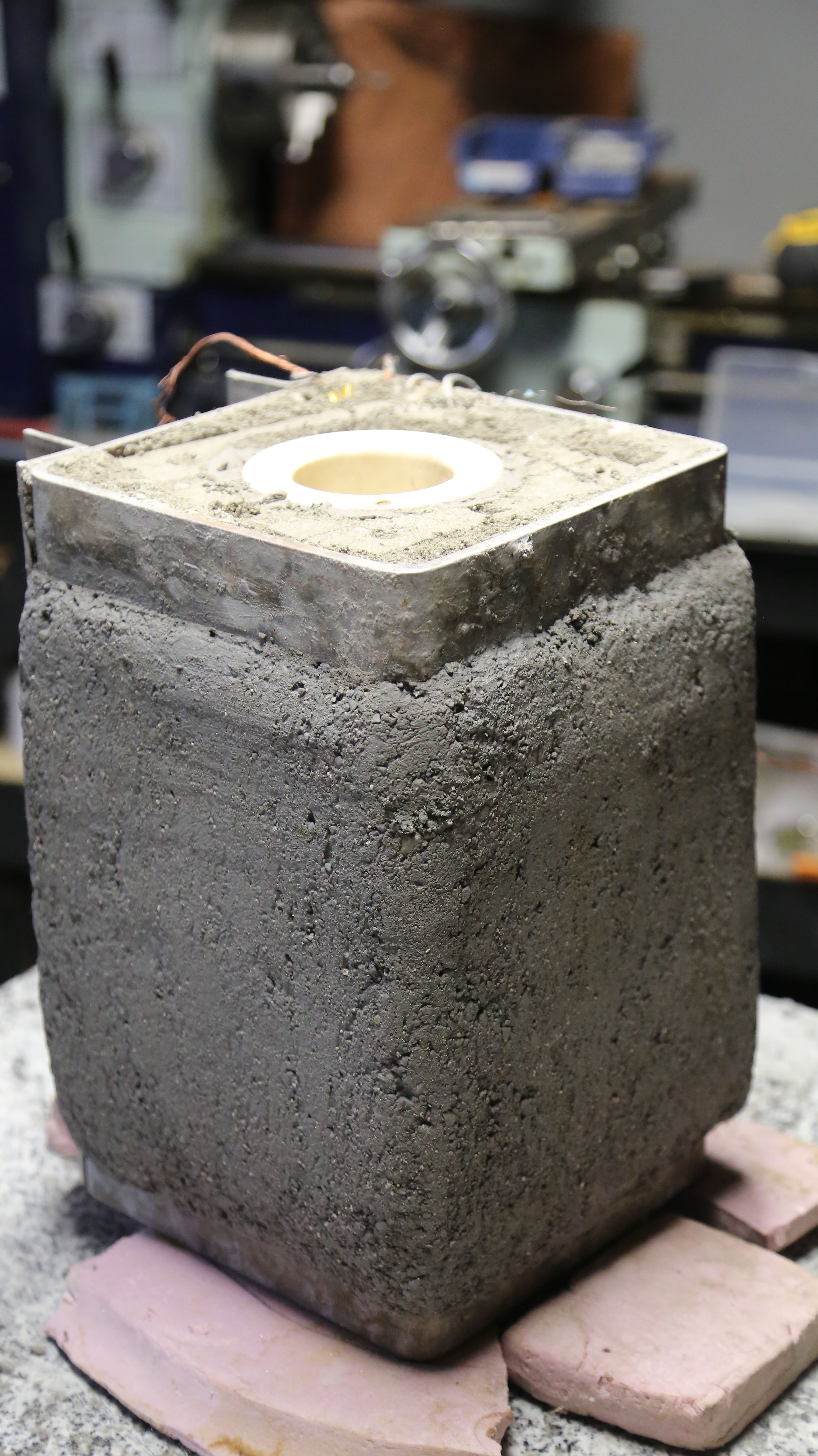
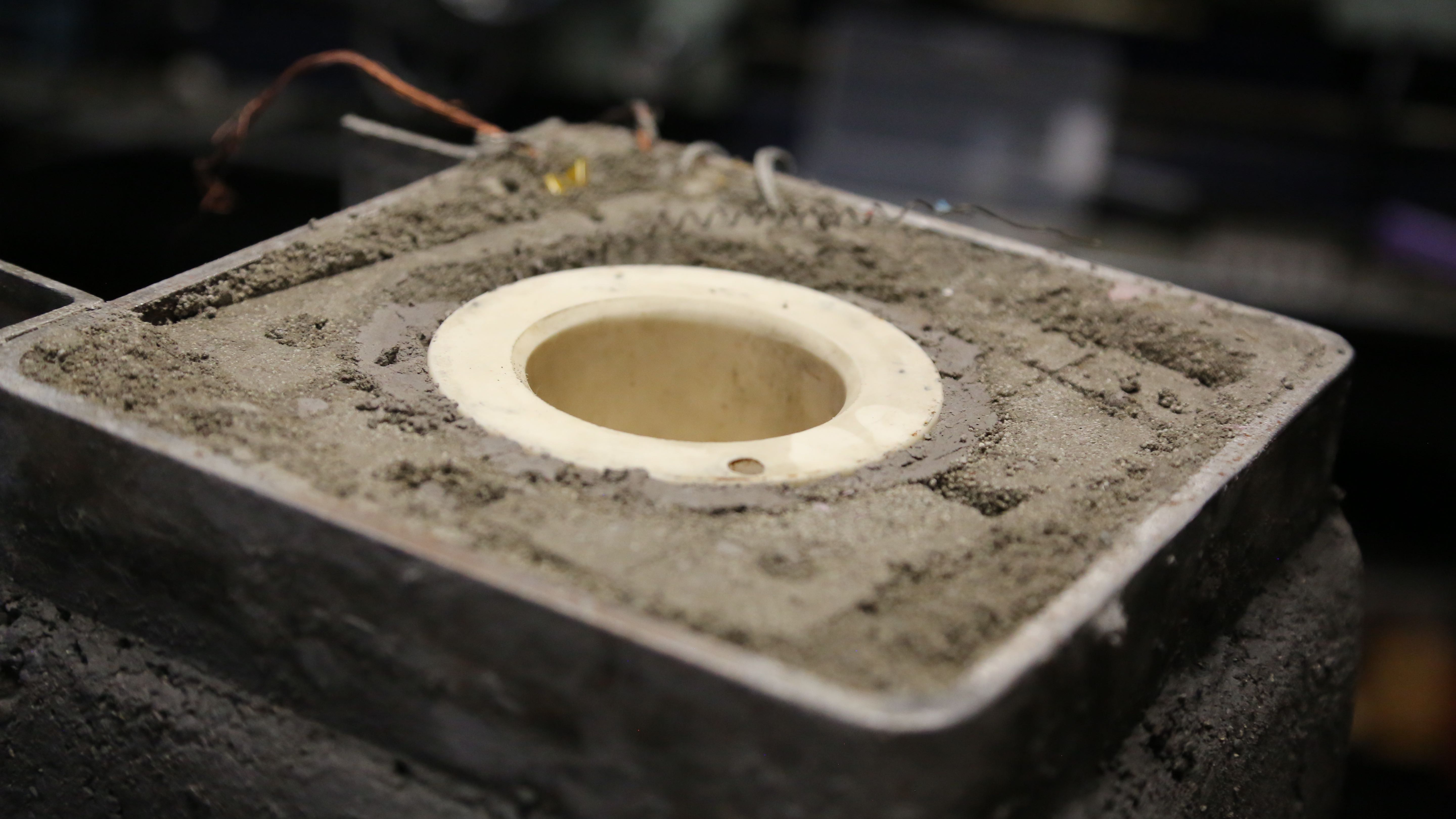
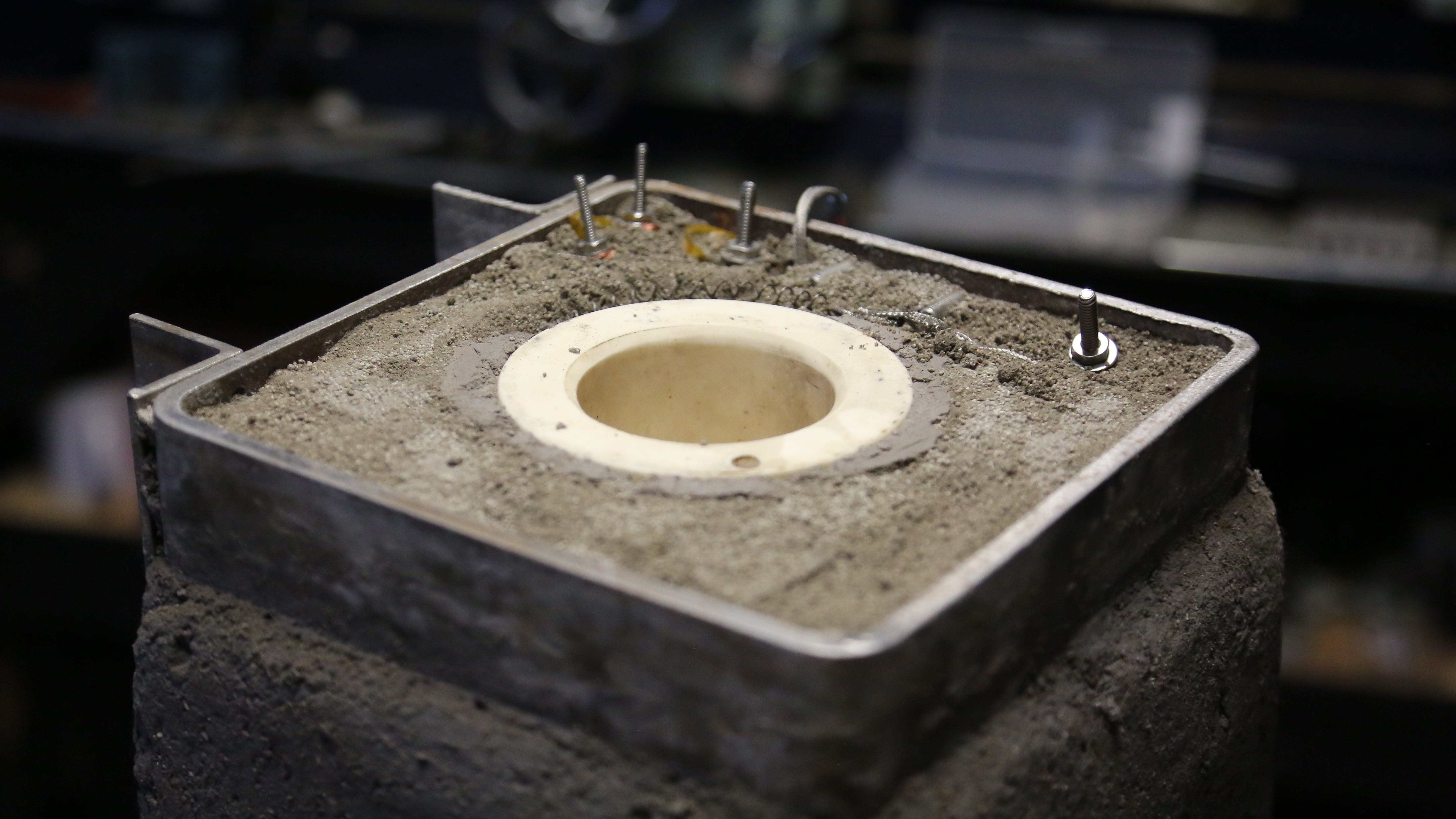
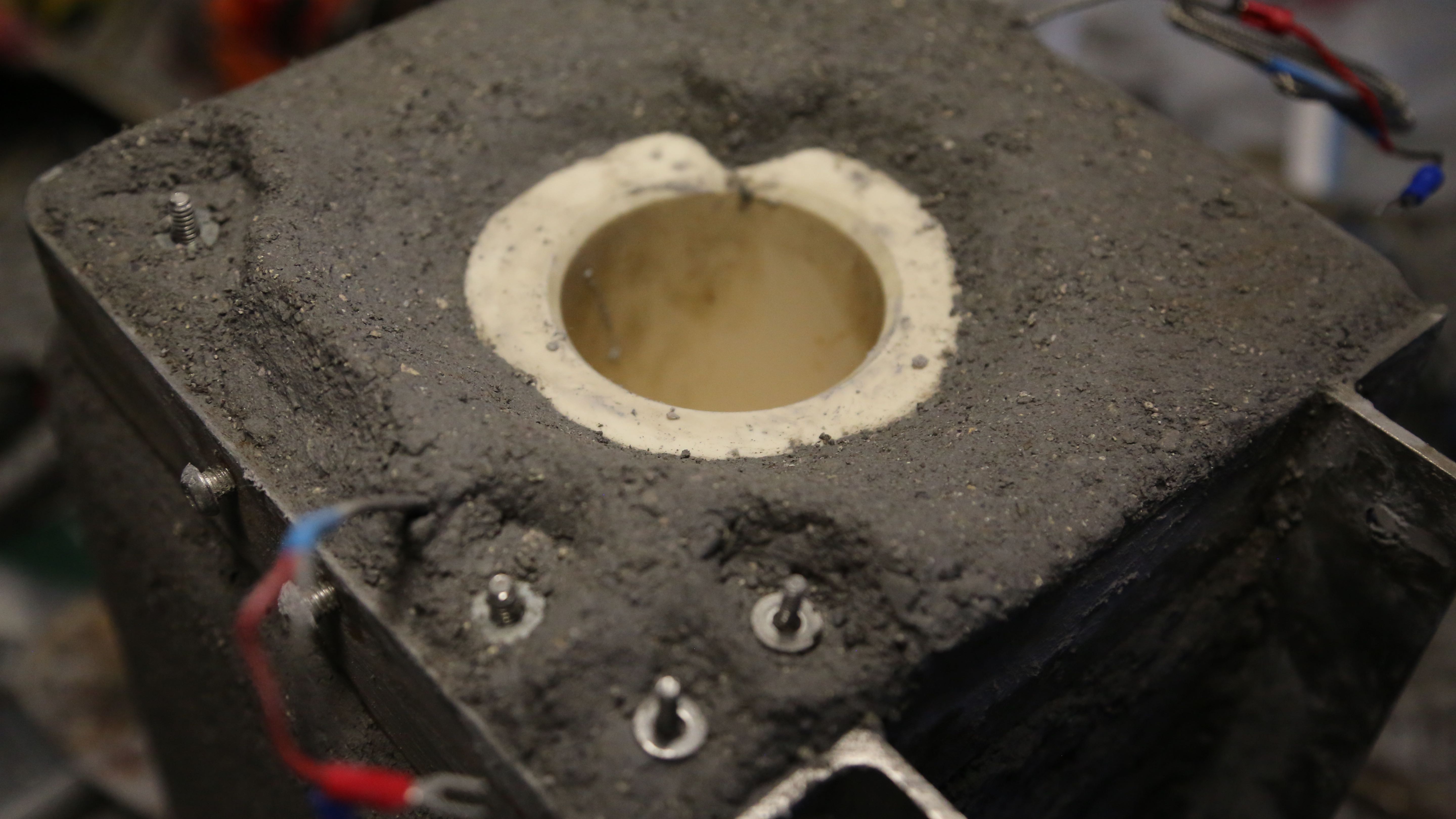
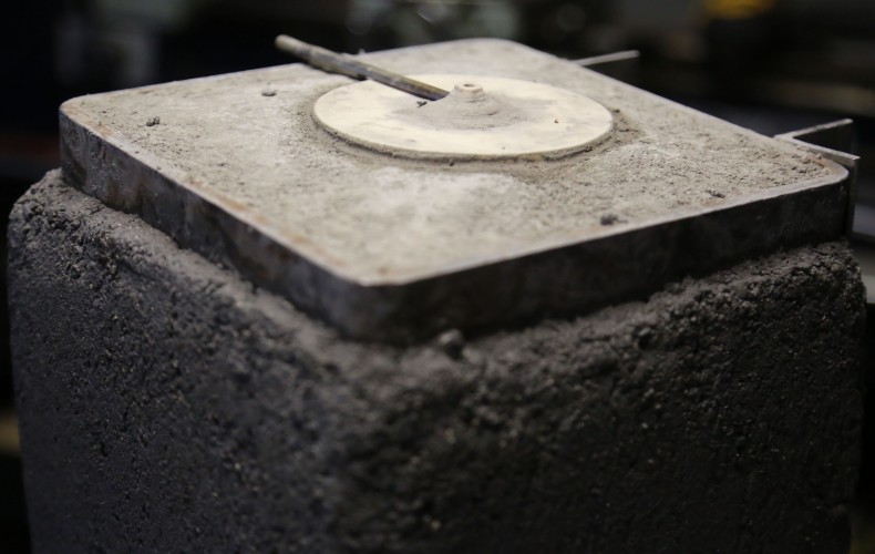
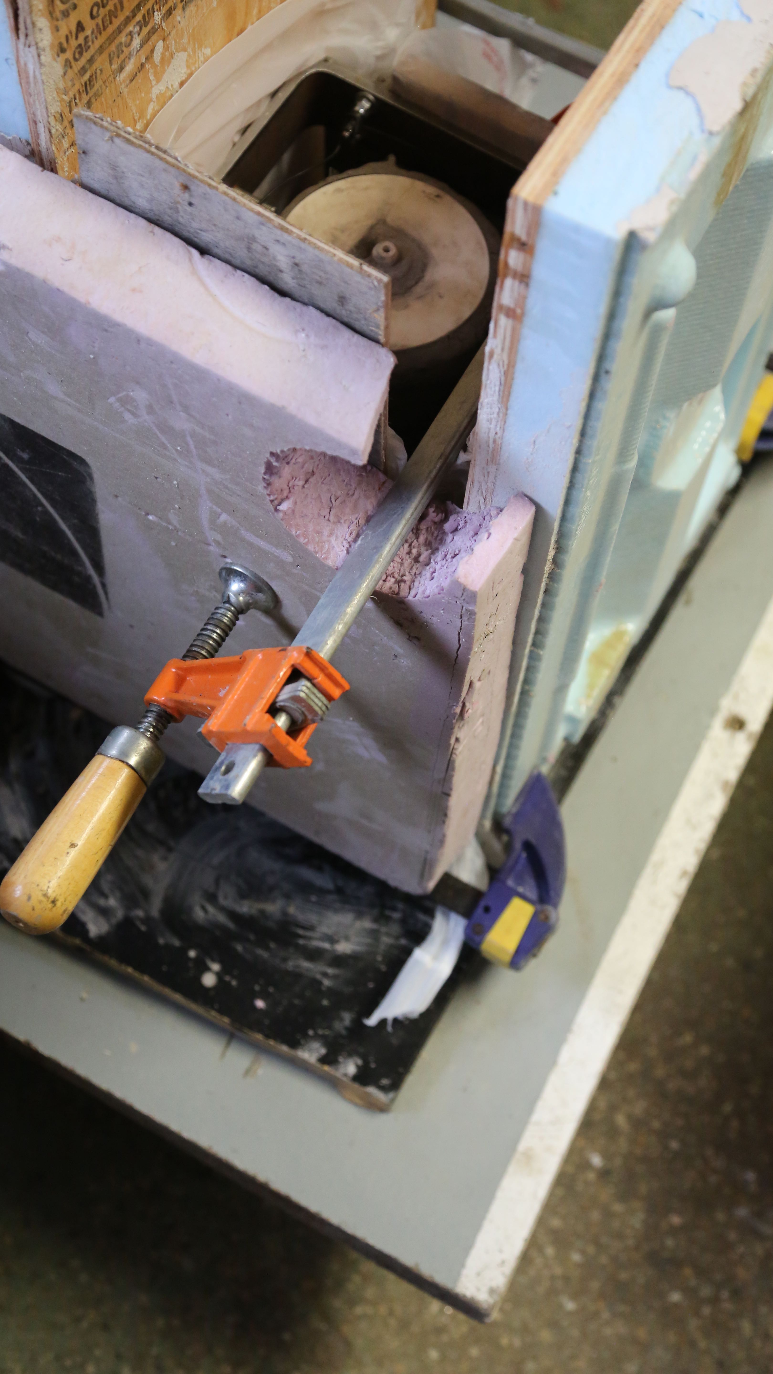
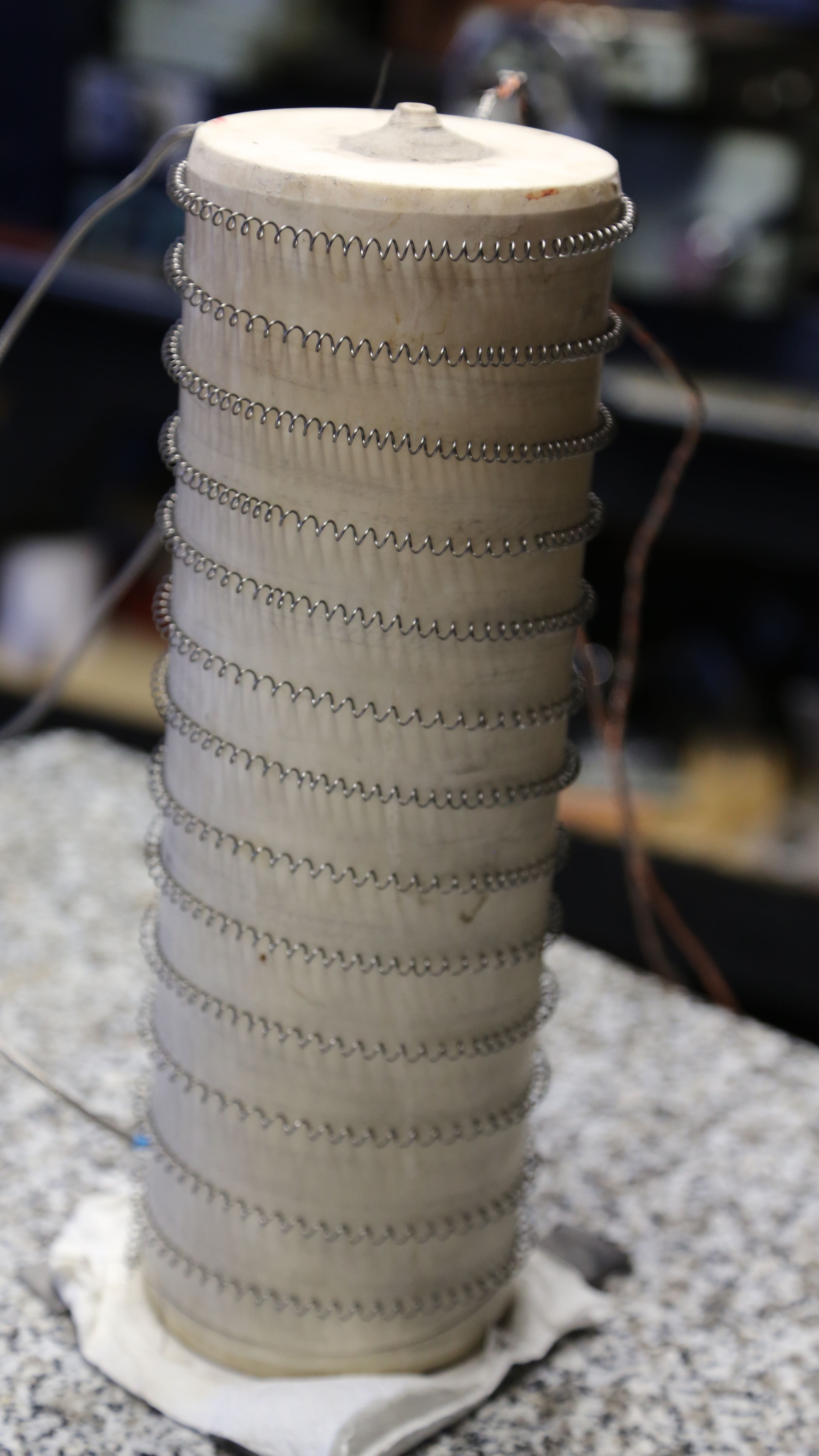
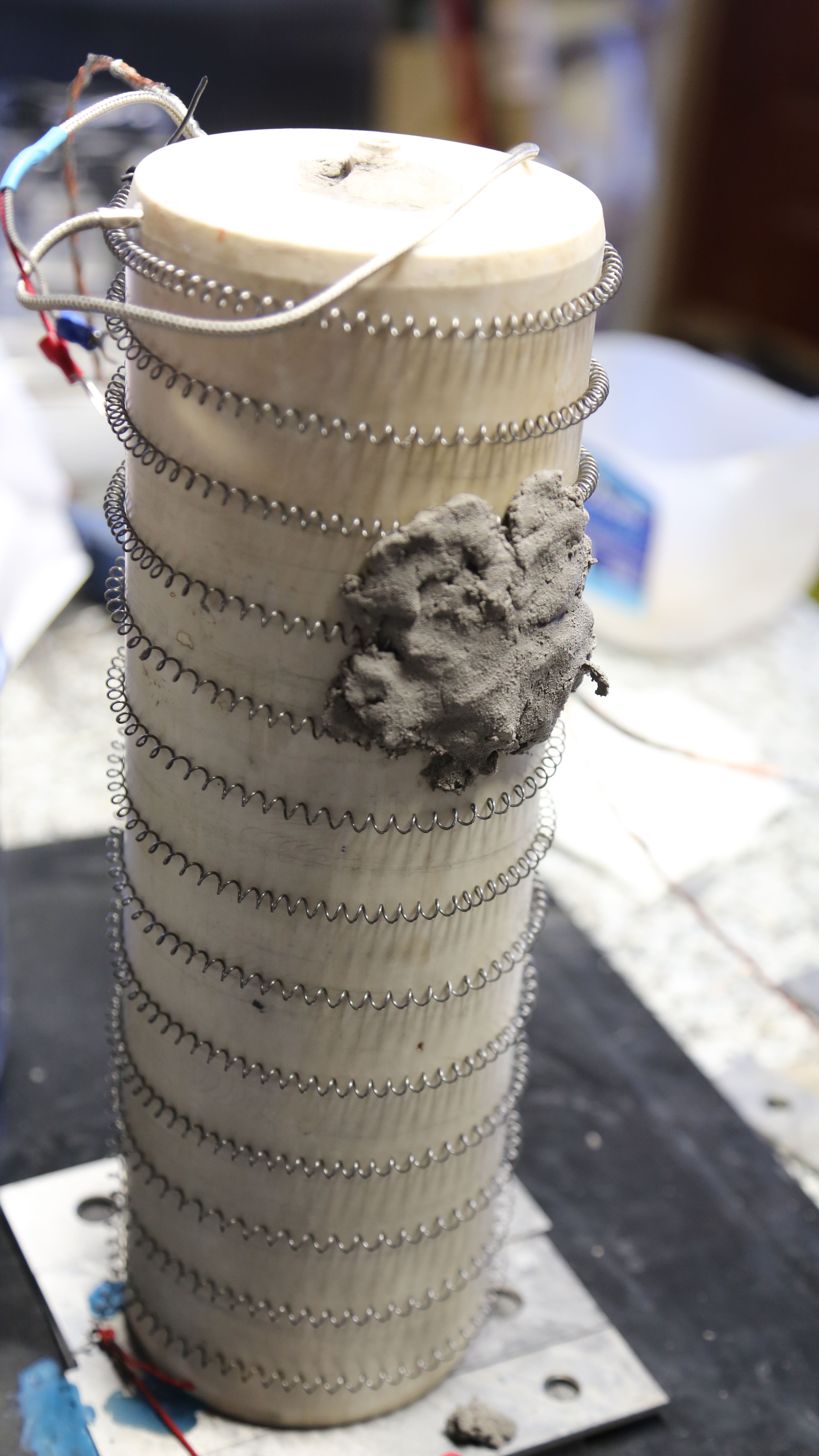
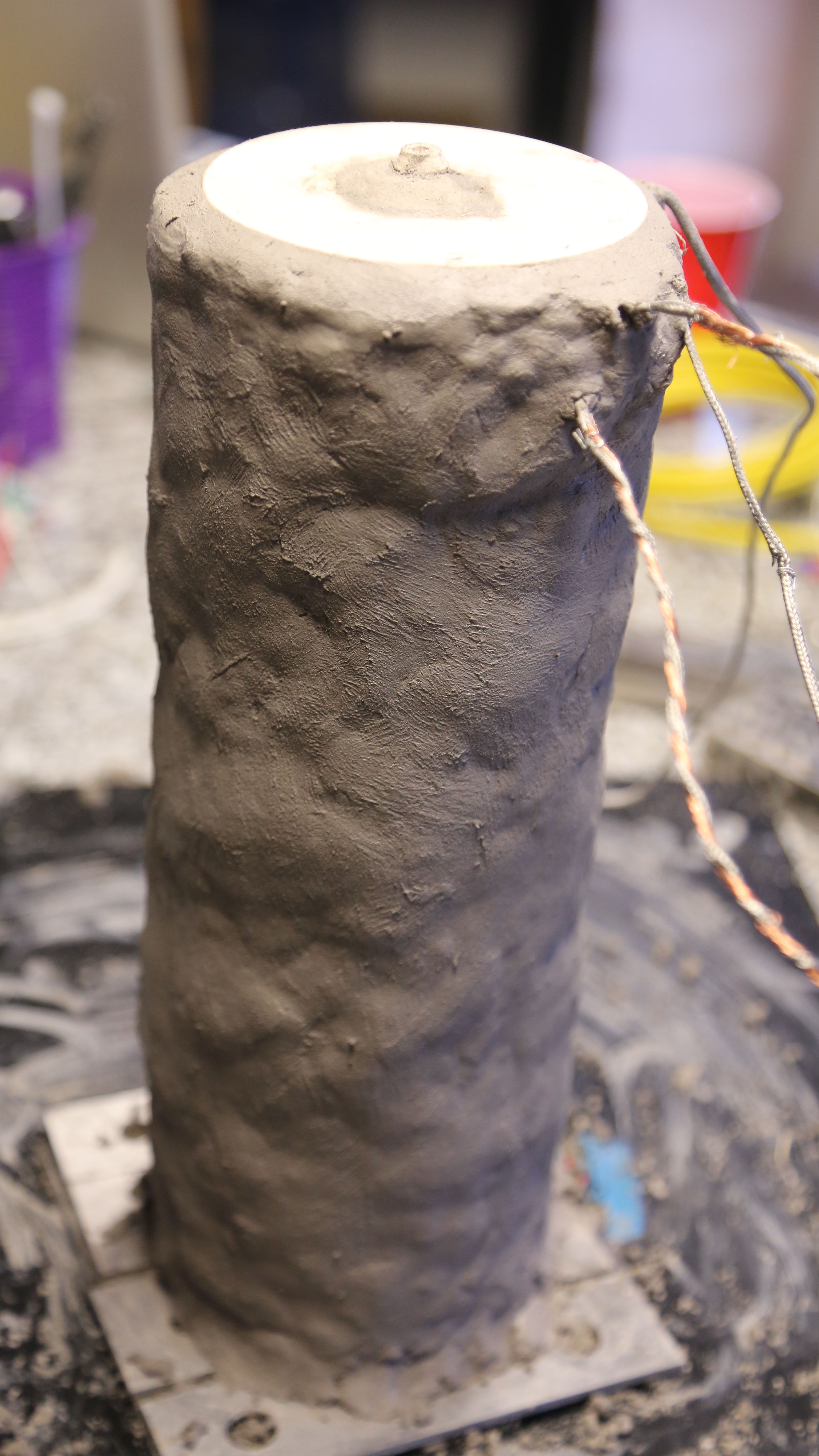
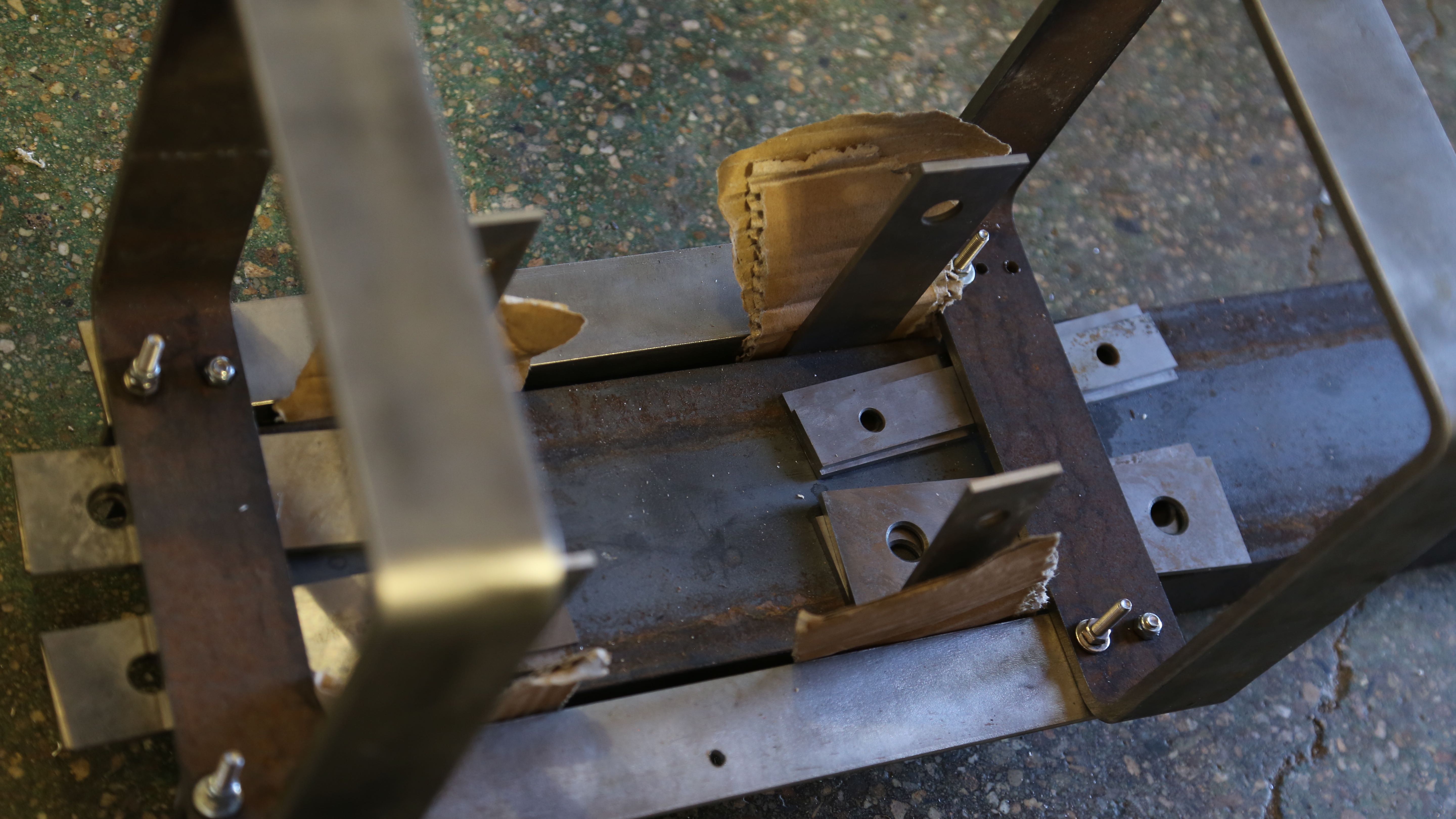
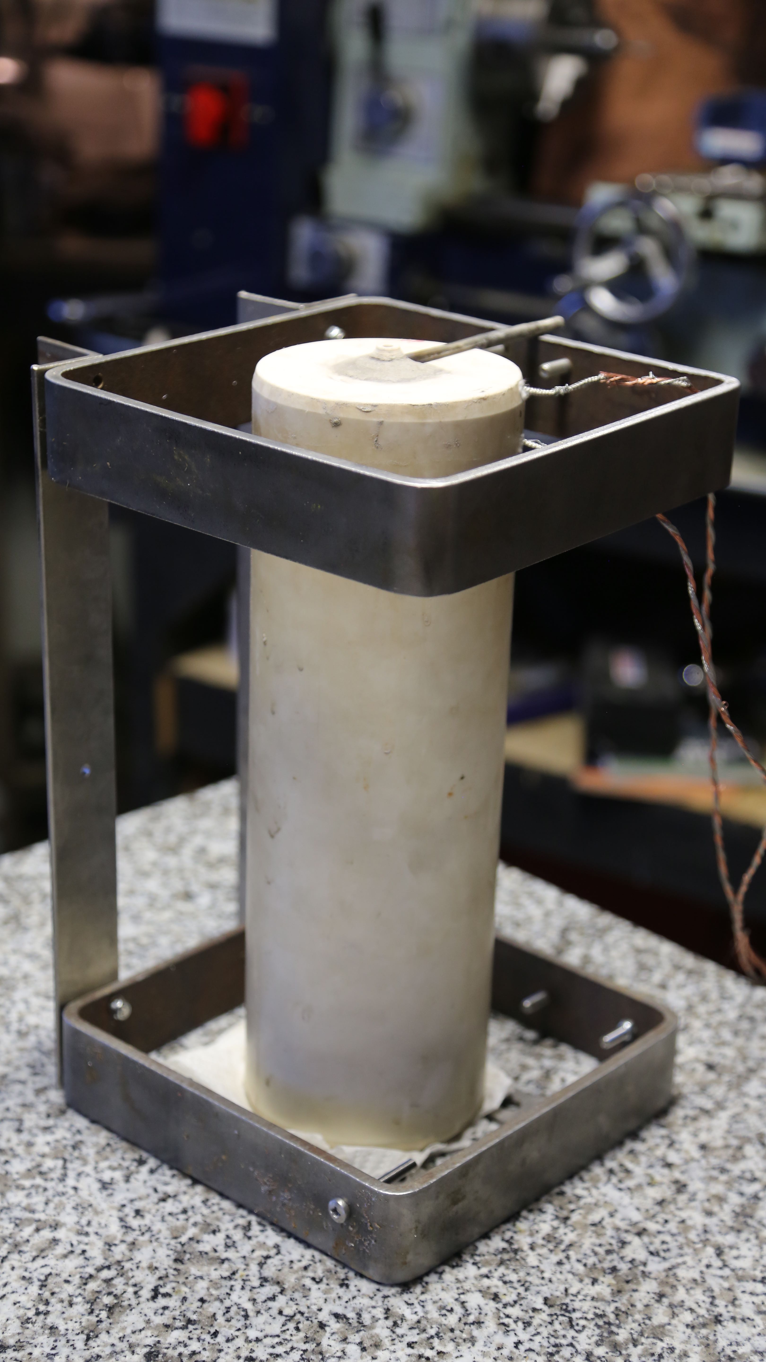
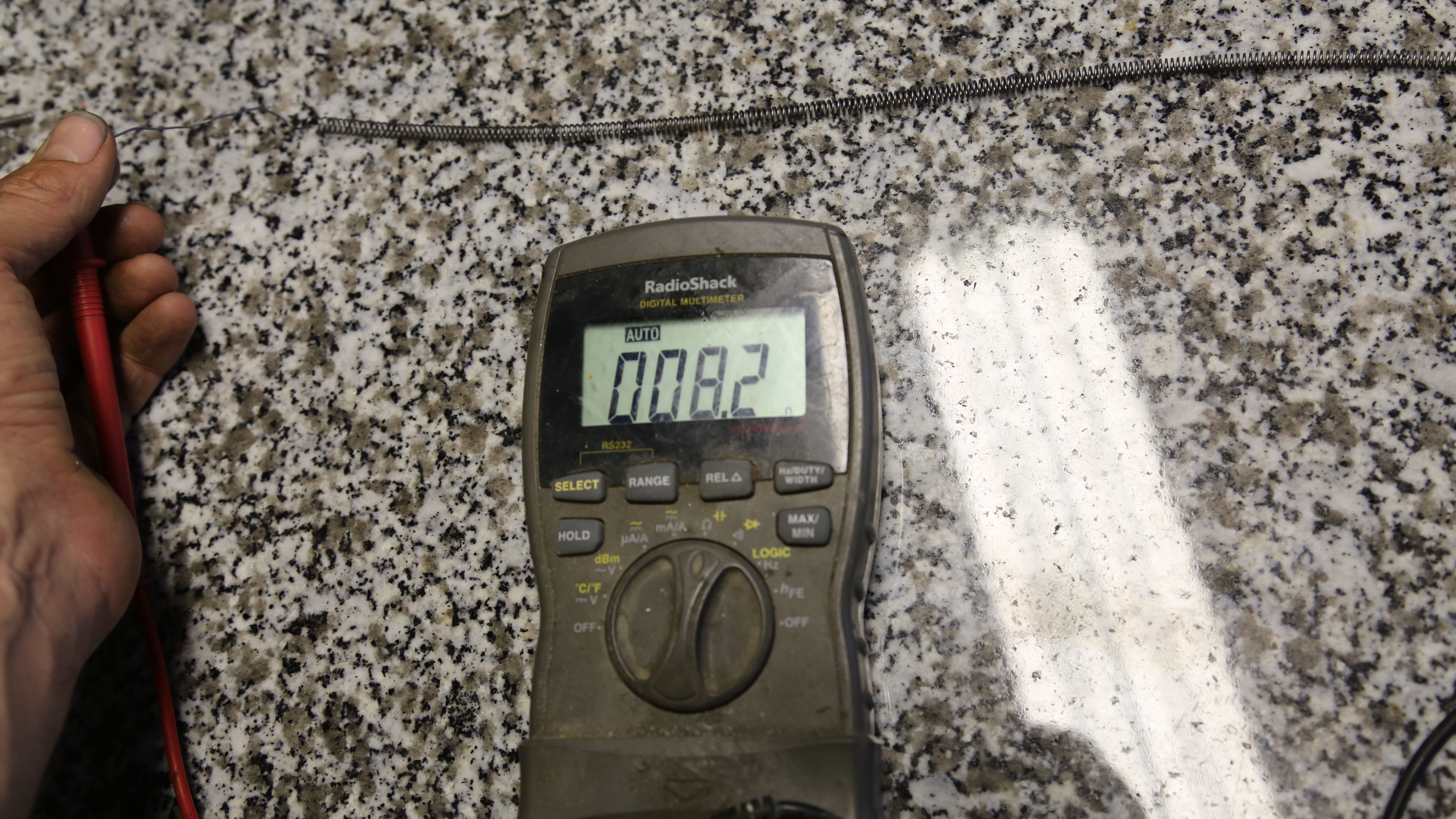
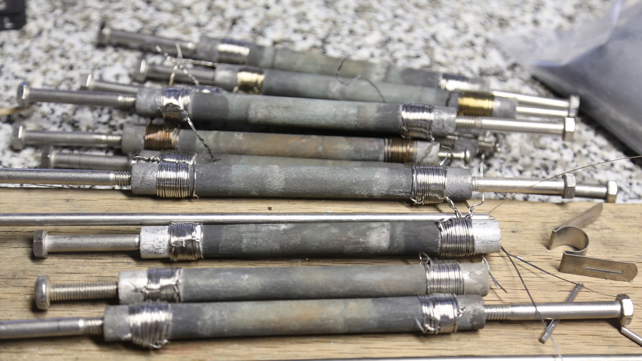
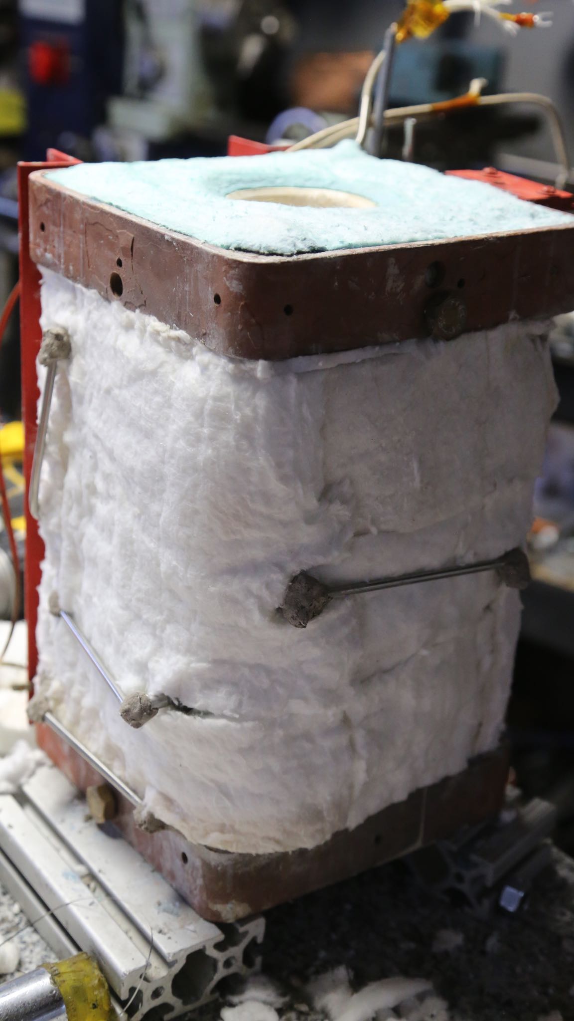
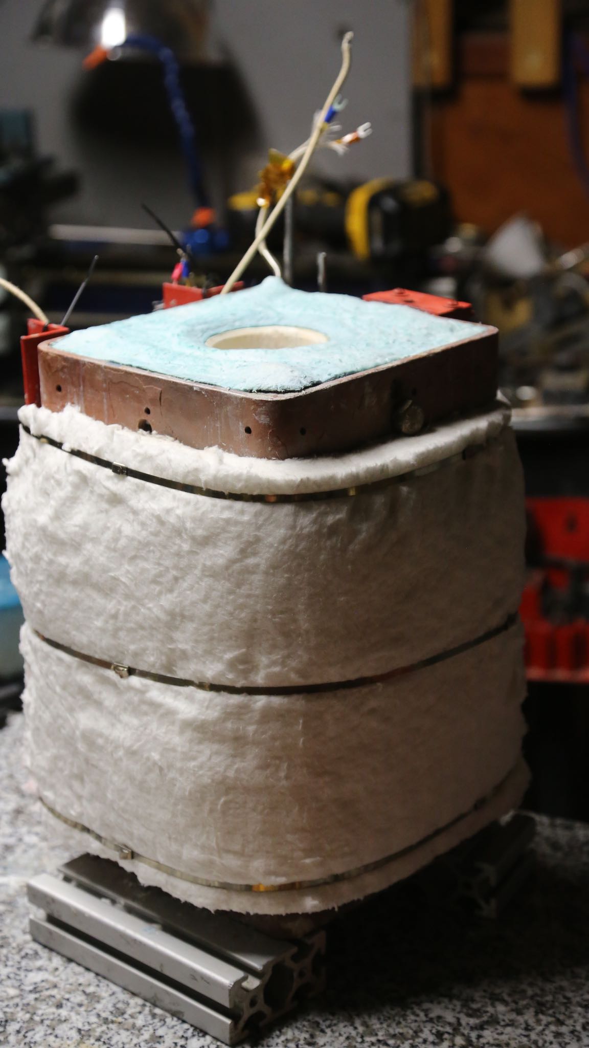
This post has been a while in the making; my apologies. It turns out that it is one thing to run an electric load at room temperature, and quite another altogether to operate in the confines of a super compact, 2000F furnace that itself is intended to operate inside a toasty 800F furnace – continuously. In other words; the wiring to service our SiC heater rods was vastly underrated for its operating conditions. With sorrow it became clear that we had to strip down the whole furnace and rewire each and every rod. For our last attempt we ran 8 strands of 18 gauge stainless steel wire. Since oxidization is our enemy, we went with solid 6-gauge (or better) stainless steel rod. It is worth noting at this point, that a typical furnace of similar capability would be much larger. Every effort has been made to keep it compact as possible since it will be mobile and takes from our usable print area.

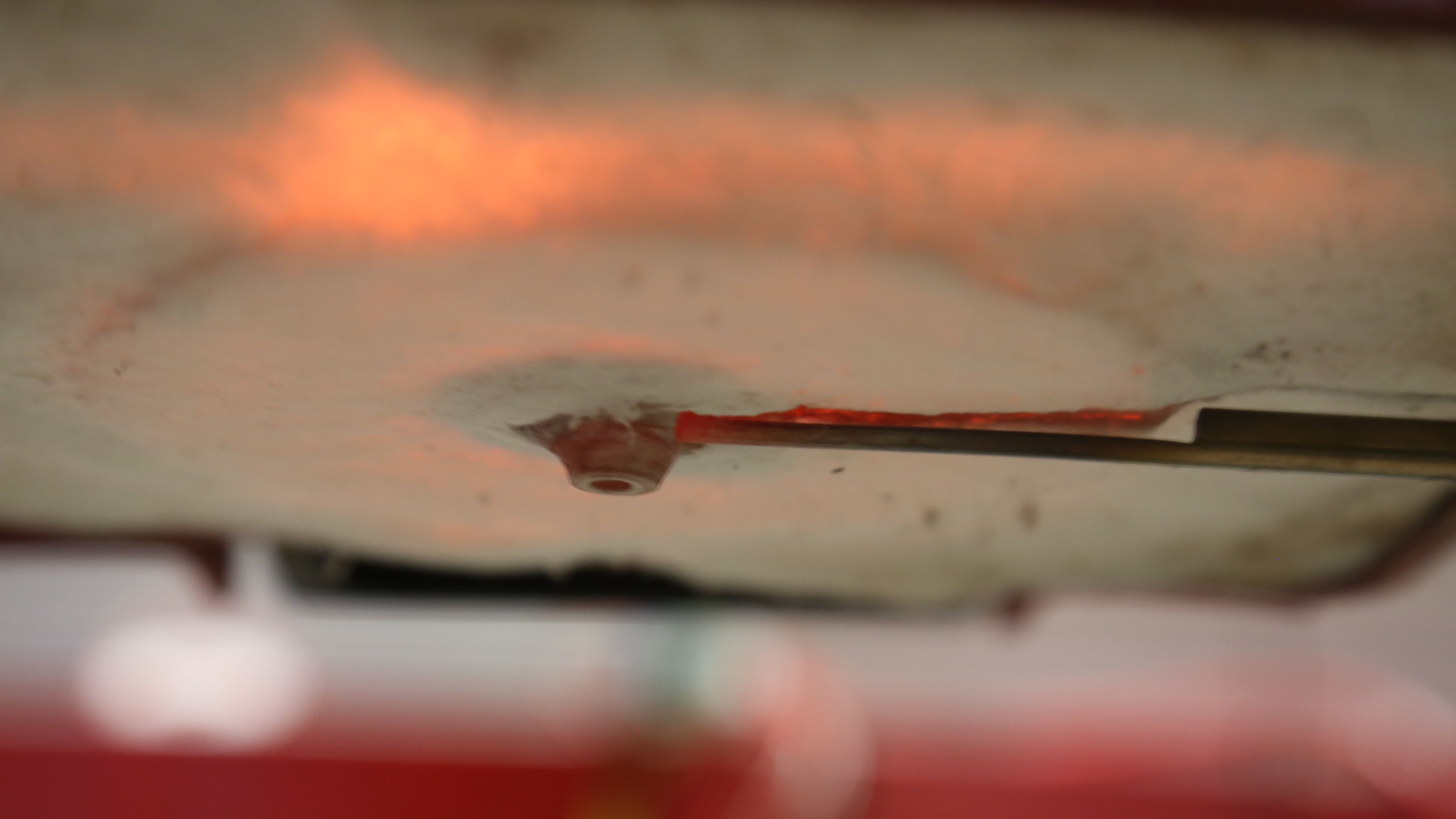
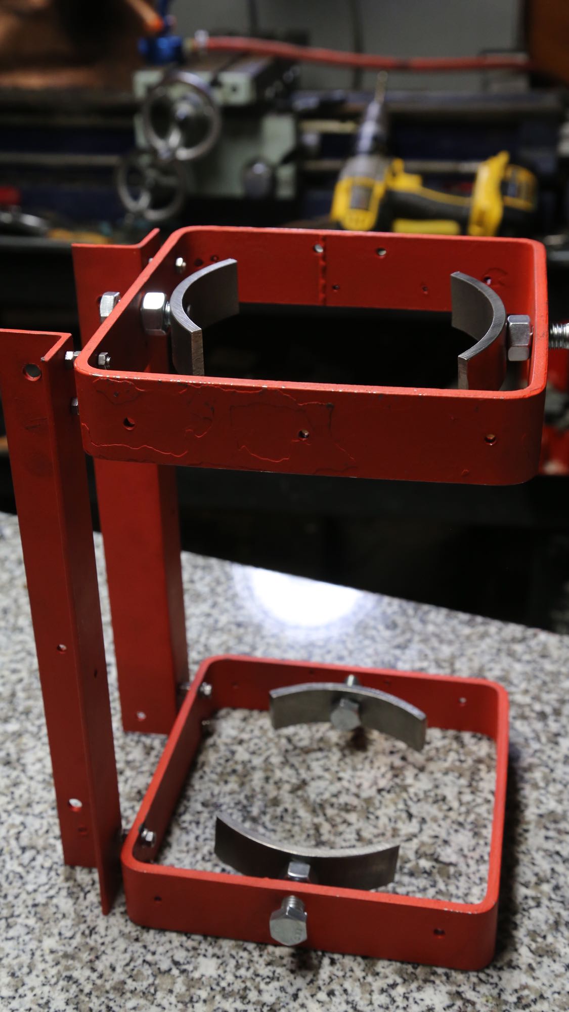
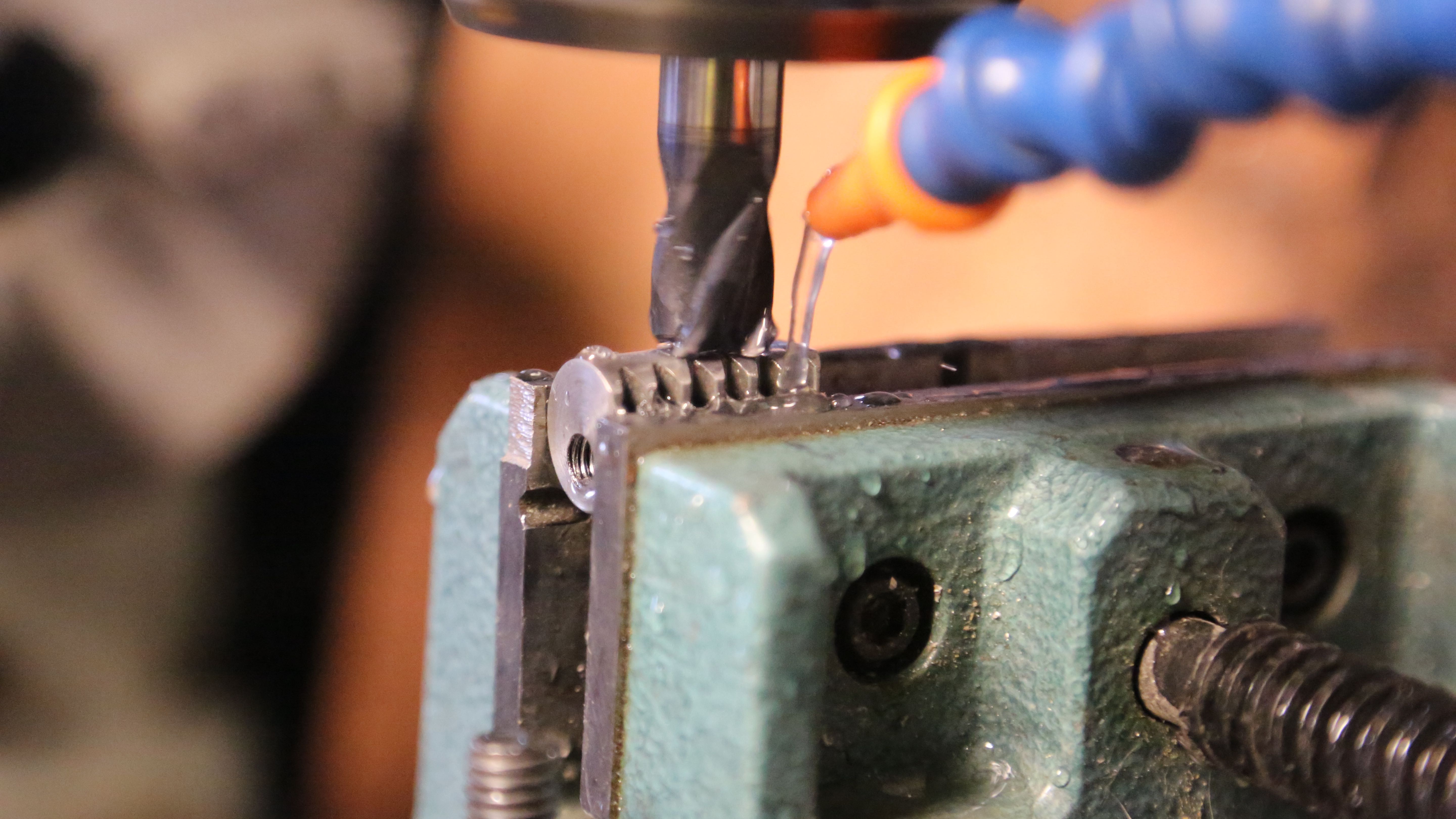
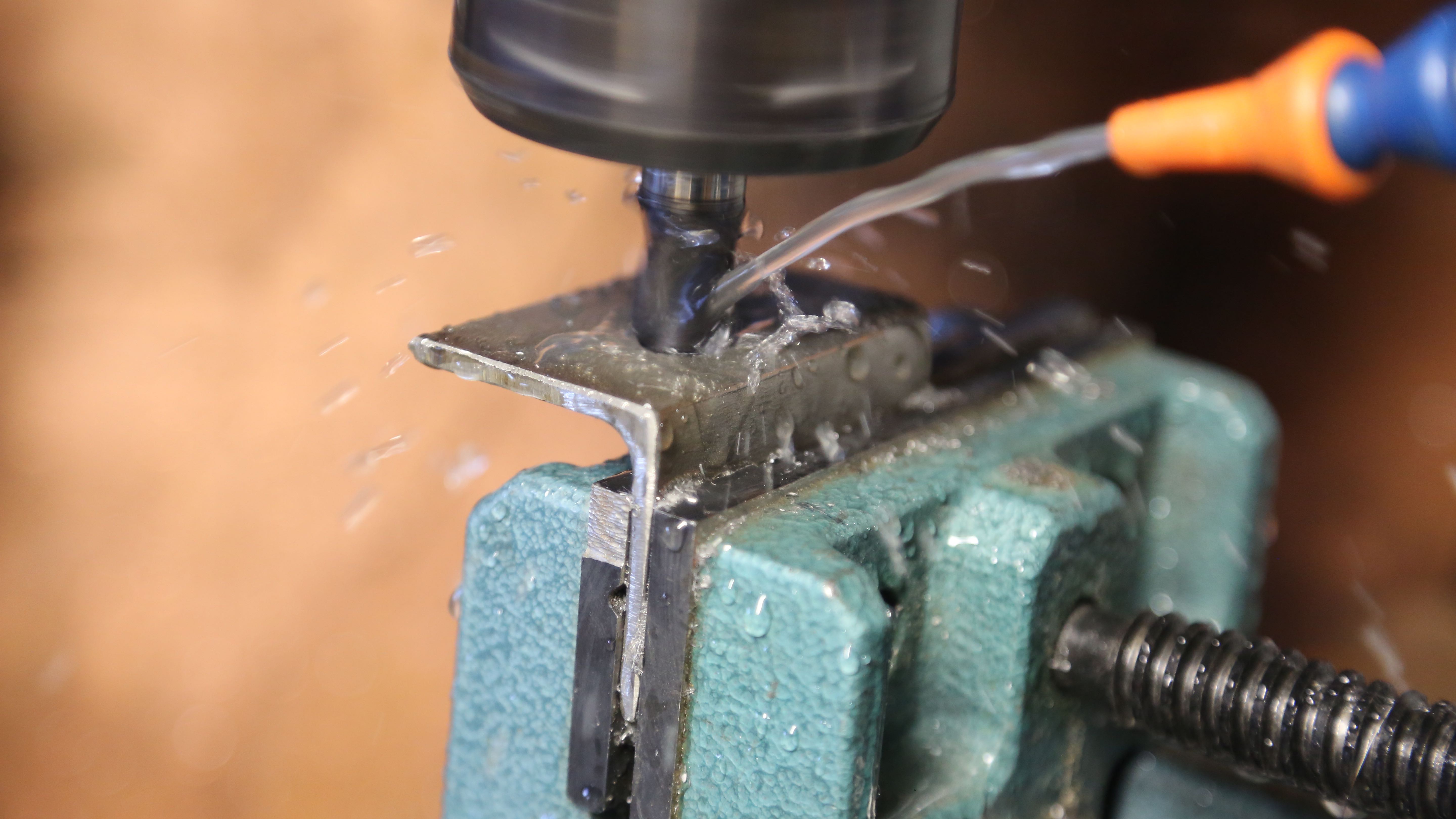
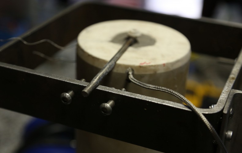
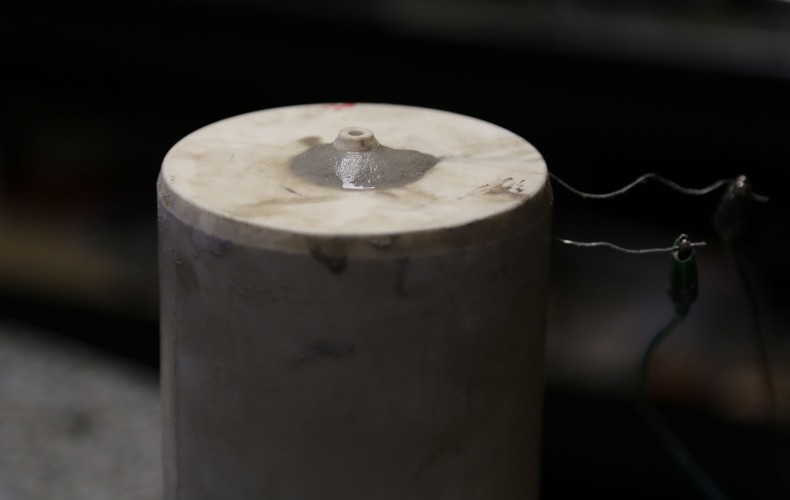
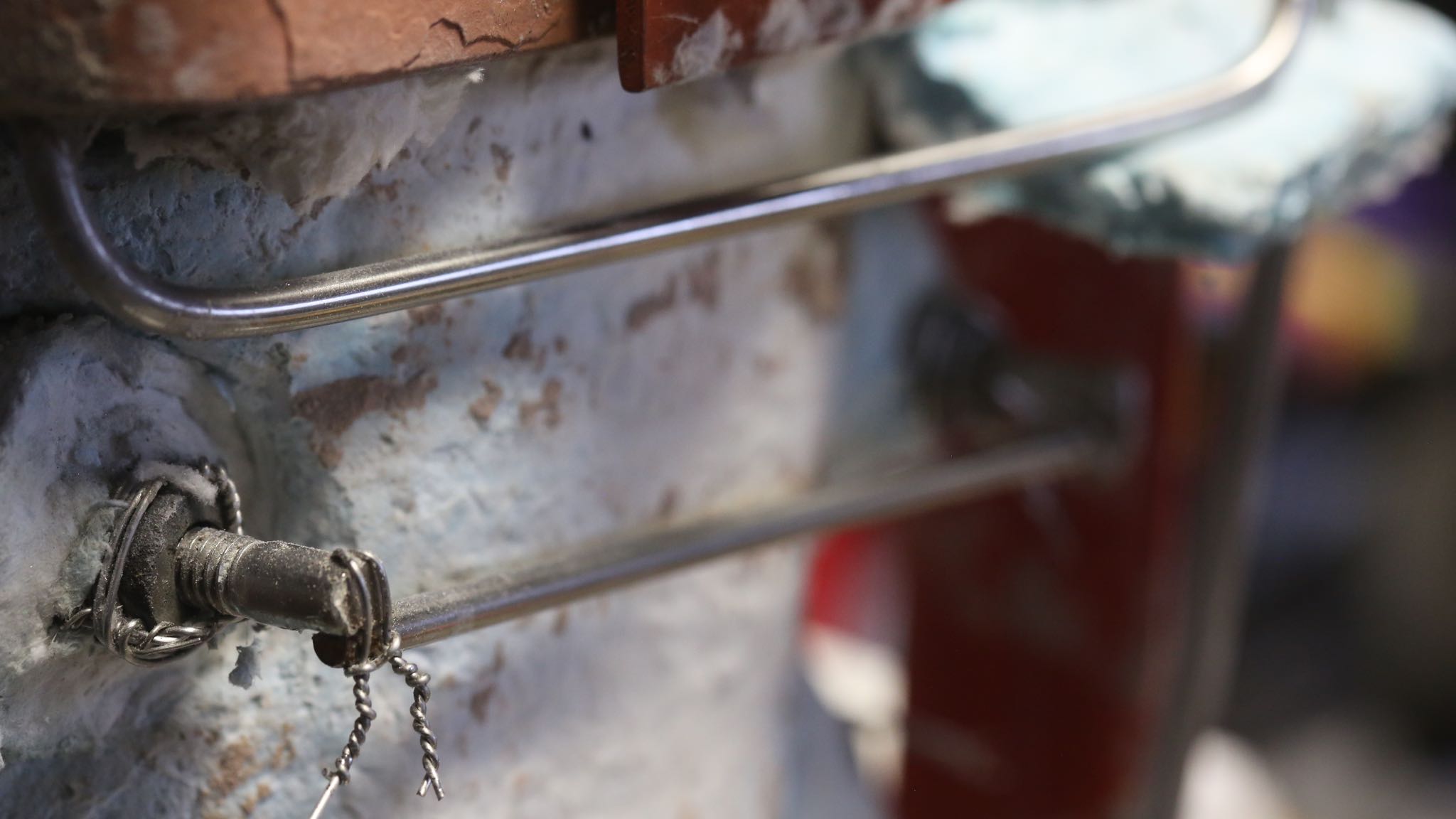
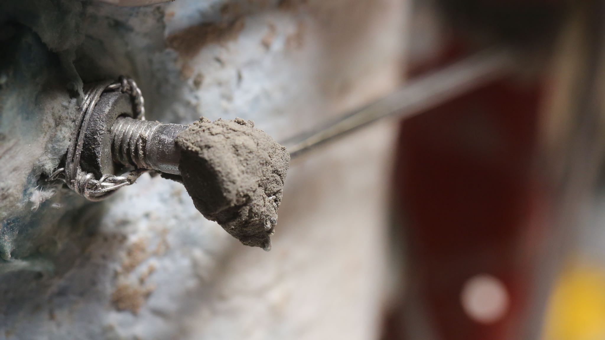
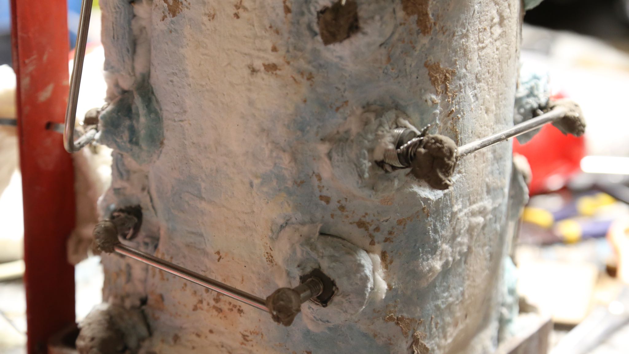
Also, the connection contacts to the rods where the weakest point in wiring system, so we painstakingly tapped out each end of the SiC rod to accept 3/8″ stainless steel bolts. This alone will allow our cool ends to operate much much cooler, and since it eliminated the need for connection clamps, it doubled the length of undersized cold ends. Win/Win!

The stainless clamp (top) is what we where going to use for new connections. After a test fire they lost their springiness, and where of a worrisome gauge. So we went with stainless steel blogs shown instead.
The thin stainless clamp (top) is what we had planned to use for our new connectors. After a test fire they lost their springiness, and where of a worrisome gauge. So we went with solid stainless steel bolts shown instead. Slightly beefier looking?
Lots of stainless steel bolts to cut, mill, drill and connect. We also used over 30 yards of stainless steel to "reinforce" the cold ends (the better the cold ends conduct the less heat they produce).
Lots of stainless steel bolts to cut, mill, drill and connect. We also used over 30 yards of stainless steel to “reinforce” the cold ends (the better the cold ends conduct the less heat they produce). We ended up wrapping the stainless wire all the way to the bolts. Can you tell which rods have been test-fired?
We used 0.1875" (6-gauge) or larger stainless steel rod for all the wiring.
We used 0.1875″ (massive 6-gauge) or larger stainless steel rod for all the wiring.
Each rod connection point is protected with 3000F refractory.
Note the refractory capped stainless steel connections.
Note the refractory capped stainless steel connections. Ready for the first wrap of non-rigidized insulation.
Complete wrap of 2nd layer on insulation, ready for the final wrap.
Final wrap of a ceramic blanket (giving it 3 inches total) and all but ready to hang on the machine again. Rejoice.

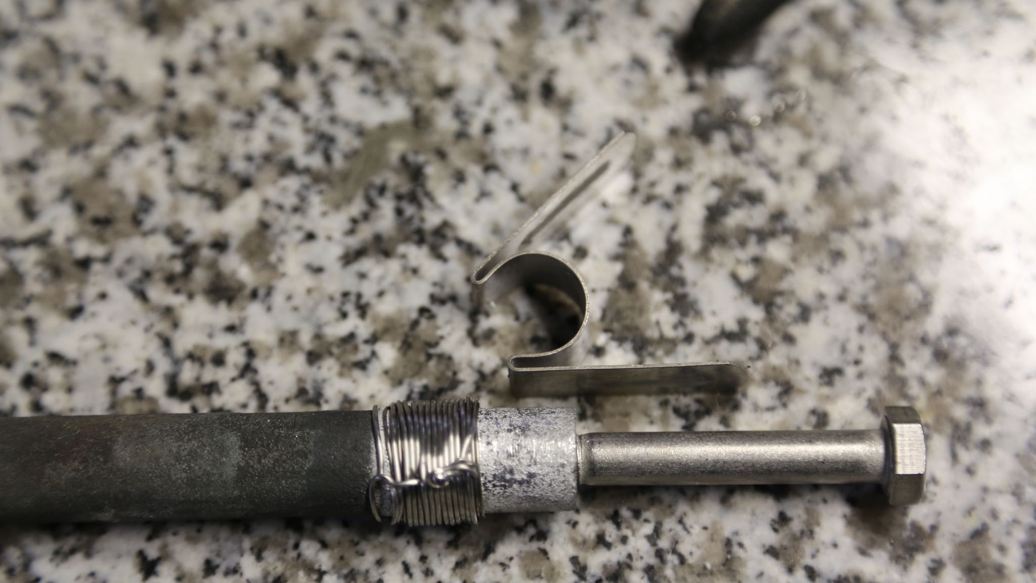
While it took tremendous effort to completely rewire our furnace, I am hopeful that it should last the life of the SiC heater rods themselves which are designed for many thousands of hours of operation. So I hope we don’t have to take it apart again anytime soon.

First Glass Melt!

First Glass Melt!

On a much more uplifting entry; we succeeded in melting glass (Studio Nuggets 96) on our machine for the first time last night! We got the crystal clear stuff up to 1100 Celsius (over 2,000F) and was nearly fluid as water! However, our thrifty SCR used to control the nozzle heater was not up to par for the current it wanted to draw (it is a low voltage high current monster) so we had to reluctantly ladle the glass out. We need to redo some minor things but all in all it was a success!

Our first ingots to be melted. Looks like Ice!
XB7A2355
All nice and melted now, took a tad more heat than ice however.
XB7A2374
Our nozzle was exposed to room temperature (versus an 800F annealing oven) and the nozzle heater’s cheapo SCR failed, or the glass would have been flowing like honey at this point!
XB7A2382
Definitely glass and definitely not printed. Still pretty exciting nonetheless.

We are looking forward to the next run!

Murphy and his Law. ZAP!

Murphy and his Law. ZAP!

Evidently in my last post I was reckless enough to challenge Murphy by taunting: “Looks like we should be printing our first glass tomorrow!”. It turns out that a couple of seemingly insignificant mistakes met for one big 7,000 watt ZAP setting us back weeks. Our machine’s (once perfectly working) sensitive motion controller took way more than it was designed for cooking components all the way up to the PCI card in the computer. We are mostly back to operation now with three of our four axes on the machine fully operational (X, Z and A). We have Y narrowed down but at the time it is not operational yet.

XB7A2379
The culprit! It is somewhat ironic that the insulator of our wire is what caused the short circuit! You can see how hot it got from the color of the braided stainless steel.

The “insulation” of our wire made unintentional contact with our 240 volt 30-amp service, but only because we wanted to see how the crucible furnace behaved before insulating it. That said, we have learned from our mistake and as a result the machine is much safer for it. Now for critical things we say “that shouldn’t happen” we have it covered at least once or twice it the event it does happen!

Swapping my super awesome Pico Systems servo controller wire by wire
Swapping our super awesome Pico Systems servo controller wire by wire
First Light

First Light

We have ignition! Our printer’s crucible was fired up for the first time (and on the machine) tonight with flying colors. She’s running 1,600F+ in open air (no lid), at about 2/3 power and using only a fraction of the planned insulation.

Looks like we should be printing our first glass tomorrow!

Furnace Re-insulated

Furnace Re-insulated

A naked furnace frame wouldn’t run very efficiently, so time for some fluffy 2600F-rated spun alumina (industrial sapphire) blanket.

We used a scrap of copper for a form and added a 1" layer of blanket around it.
We used a scrap of copper for a form and added a 1″ layer of blanket around it.
Looking nice and cozy already with more insulation to come!
A soft floppy blanket won't do as a frame to hold our SiC elements (coming soon) so we soaked the alumina blanket in colloidal silica to rigidize it (once it is dry)
A soft floppy blanket won’t do as a frame to hold our SiC elements (coming soon) so we soaked the alumina blanket in colloidal silica to rigidize it (once it is dry)
We made sure the blanket was soaked good. The orange tape was a temporary form to keep the blanket from sagging under its wet weight.
After not long it was stiff enough to remove the tape, though still quite colloidal-logged.
Wrapped up! Still wet with colloidal silica but she is really starting to look like a toasty furnace. We'll probably add one one layer of blanket - its quite light and would add considerable more efficiency.
Wrapped up! Still wet with colloidal silica but she is really starting to look like a toasty furnace. We’ll probably add one one layer of blanket – its quite light and would add considerable more efficiency.
Furnace Frame Rebuild

Furnace Frame Rebuild

Once the furnace was re-designed (prior post), of course the next step is to implement it.

Here Christian is cutting some stainless chips like a metal shop champ
Taking our time cutting the hard stuff
Stainless steel collars cut and drilled
Tap tap tap and some more tapping
Frame stripped down. Added some new threaded holes to clamp our thermal blanket.
A few coats of 2000F rated paint to protect the steel
Ready to reassemble.
We took the rebuild opportunity to add an additional thermal break
All ready for the refractory blanket insulation installation
1500C Furnace Redesign

1500C Furnace Redesign

As much as I would prefer to only report success we are learning a lot which means of course means making some mistakes along the way.

The first design of our glass melting furnace relied on a 2KW wire heater. After installing the wire we found that it only deliver 1.3KW at best. In addition, burying the metal wire in castable refractory was likely a fatal mistake, because I now suspect that the wire needs to be able contract and expand each operating cycle. Even if it didn’t there is a chance that at operating temperatures the refractory (which is a good insulator at room temperature) could have become conducive at working temps — potentially shorting out the entire heater coil.

In addition, even if the coil had operated at 2KW for any length of time (ignoring the above) it would have taken a long time to heat up and likely struggle to maintain the desired temperatures. In other words, it was vastly underpowered.

The new design is based a 7KW system comprised of Silicon Carbide (SiC) heating elements (ED shape). In addition to heating up rapidly, the new setup will allow us to operate continuously 1500C. This will allow us to print borosilicate (Pyrex®) and possibly interesting things like (fired) ceramics and de-composed granite (that is what the “dirt” we are sitting on top of is mostly comprised of).

XB7A1797
Sometimes you have to break an egg to make omelet. It was sad to tear apart, but it will be oh-so-much for the better.
XB7A1802
All stripped done ready for the much improved design. OK tearing it down wasn’t so bad after all.
Screen Shot 2015-10-14 at 1.14.04 PM
Orange is our alumina crucible. The transparent shell represents the lightweight fiber blanket that will be used in place of much heavier (and thus less insulating) refractory used previously. The blue section of each rod is the cold zone of our SiC heater rods, with the hot section shown in red. Electrodes attach to each of the blue ends.
XB7A1792
Tiny little SiC test coil running 2.0 amps at 41 volts (only 92 watts, we will be running 7,000!). Pretty much melts glass instantaneously. The 2300F rated fiber blanket bonded to it (won’t happen in our actual design).

So while it has been a bit of a misstep, it will only be for the better. Our set of custom SiC rods are currently being fabricated in China and will hopefully ship to us this week. All other aspects our massive printer have been tried and verified to work. More soon.

Heating Up

Heating Up

We now have our heat electronic control box installed on our great big printer and starting to test things out. Here our annealing oven is heating up for one of the first times.

Print Chamber Installed

Print Chamber Installed

We now have the print chamber finished and installed on our massive machine. The chamber will be operated at a toasty 800F during printing glass (it will be put to use for pizza firing undoubtedly after a days run) that allows the inter-printed layers to adhere (and at optical quality), grow without warping and or cracking and to anneal so a printed piece doesn’t self-implode at some time in the future.

Our 21" diameter kiln shelf will ride on springs. We have found this to be a critical feature for FDM printers we have used.
Our 21″ diameter kiln shelf build platform will ride on springs. We have found this to be a critical feature for FDM printers we have used.
Our 4KW stove element is connected 1000F rated wire. Nice stuff!
All insulated and looking toasty. We will be able to print objects larger than the 21" kiln shelf.
All insulated and looking toasty. We will be able to print objects larger than the 21″ kiln shelf.
Whatcha' got cookin'? The widow is actually transparent ceramic - not glass
Whatcha’ got cookin’? The widow is actually transparent ceramic – not glass
Nozzle Rack & Pinion

Nozzle Rack & Pinion

In order to control our stainless steel nozzle actuator from a more reasonable room temperature, where standard stepper motors merrily step to and fro, we needed to transfer the power to outside our 800F print chamber. For that purpose it seemed that good old rack and pinion was the ticket.

Machining the round rack on one face so that it can't rotate bound against a soft graphite bushing
Machining the round rack on one face so that it can’t rotate bound against a soft graphite bushing
Cutting a slightly oversized hole in some stainless angle stock. The graphite bushing will be to actual size of the shaft diameter
Machining the graphite block. Graphite works at high temperatures and is nice and soft (its essentially pencil "lead")
Machining the graphite block. Graphite works at high temperatures and is nice and soft (its essentially pencil “lead”)
We are happy to report the design is working flawlessly!

Being able to actively control the nozzle should allow us much greater control (it can actively restrict the flow rate), allow us to print any form without restriction (other than support restrictions inherent to the FDM process), and we think it should be able to print molten metals (aluminum, copper, etc) in a similar fashion as glass.

Refractory Dryout

Refractory Dryout

Our precious crucible cart has undergone its final transformation into what will likely become the key element of our glass printing machine. Unlike portland, refractory does not use good ol’ H20 for its chemical bound, so for refractory, firing is a key step.

XB7A1583
Furnace Fractal? After we slowly ramped the temperature of a kitchen oven up to 400F it was time to put it in our furnace to gently ramp up to over 1200F. If the refractory is heated too quickly (first time) you run the risk of steam explosions ruining all your hard work or the refractory not maturing to full strength. Starting flame shown.
Getting warmer. Added some fiber blanket in the back to shield it from direct flame.
XB7A1605
Warmer!
Hotter
Hotter. Our crucible thermocouple reading was around 800F – we need it up around 1200F soaked all the way through…
There we go.
There we go. Now our refractory is a lovely pumpkin color. We’ll let her bath in it for a while, but reduce BTU input – we don’t need it any hotter. Well that is until she is operating under her own power that is of course.
Desired tempter reached and maintained for a while.
XB7A1635
Cooked until perfection
XB7A1636
Resting temp at 572C (1061F). Covered the furnace with extra blankets to let some of that trapped heat soak all the way through and slowly cool overnight.

Next time you see our crucible cart it should be mounted on our machine!

Final Refractory Work

Final Refractory Work

One last chapter before we can begin our crucible cart’s dryout schedule: the top. We need a bomber top to handle ladling of molten glass blobs into the crucible as well as way to fix the loose electrical terminals. The insulating refractory won’t cut it in these departments so its time for some more 3000F rated refractory to coat on top.

Here she is flipped over for the first time the following day. Looks good except the top.
We scrapped some more insulating refractory off
Before we scrapped a little more insulating refractory off. Loose wires wires evident in background.
Then attached stainless steel bolts to the 4 electrical leads (crucible heater and nozzle heater).
We attached stainless steel bolts to the 4 loose electrical leads (crucible heater and nozzle heater). Much better already!
All the electrical leads have nice bolts to attach our wiring to. They are somewhat protected by some additional refractory strategically placed.
All the electrical leads now have nice firm bolts to attach the leads to. They are somewhat protected from ladles of glass by some additional refractory strategically placed. The notch evident is to shield the crucible’s thermocouple.
Now we have to wait before putting the whole crucible cart into an oven for its firing schedule
Now we have to wait (again) before putting the whole crucible cart into an oven to meet its firing schedule. To be continued…

After its fired we can get it mounted to the machine and should be showtime!

Insulating Refractory Installation

Insulating Refractory Installation

Now that we have that big (potentially) hot heater coil wrapped about our crucible, its time to give her some insulation to keep those precious BTUs where we want it – melting glass (or whatever else we may find ourselves melting with our new contraption – mooohahaha).

Alright, so now after carefully placing our crucible cart onto our vibrating table we clamped forms around the sides ready for filling. In all places where there was potential wood contact, we covered said wood with plastic bags to prevent it from adsorbing an unfair of moisture from the curing refractory.

On our vibrating table - ready for filling with 2500F insulating refractory.
On our vibrating table – ready for filling with 2500F insulating refractory.
Refractory isn't portland - its typically applied much more dry.
Refractory isn’t portland – its typically applied much more dry – very dry.
All filled up, now it has to sit for at least 24 hours covered with plastic.
We scrapped off some of the frail insulating 2500F refractory after it came out of the forms. Then we troweled on a generous shell of much more durable 3200F refractory. Then wrapped with saran wrap for 24 hours.

Then we get to flip it over and finish the top side – next episode.

Crucible Heater Coil Packed

Crucible Heater Coil Packed

With each post, our excitement grows!

Of course, if we are to melt glass, we are going to need some heat, a whole lotta’ heat indeed! So we are pleased to finally outfit our crucible a 220V 2KW heat coil and packed in a jacket of 3200F rated refractory.

Heater coil wrapped fairly uniformly
The first patch of 3200F refractory.
All wrapped up nicely, ready for cart fitting.


As we were saying; cart fitting. Added some ceramic blanket wire insulation in the iffy spots (the tape will burn away).
As we were saying; cart fitting. We added some ceramic blanket wire insulation in the iffy spots (the tape will burn away but the protected space will remain).

Next up – fill this baby with some insulating refractory to keep our needed heat in.

Crucible Cart

Crucible Cart

We got the cart all built today. The crucible isn’t much good if we can’t steer it around, and that is the the cart’s primary task. The secondary task is to provide a frame that will fill with high temperature insulation (refractory).

The third task is to provide a thermal heat break from the 2000F crucible. We selected stainless steel for that task and in addition, the stainless doesn’t make full contact with the steel it will be mounted to. So the stainless is about 1/4″ away and only make contact where it is bolted.

XB7A1453
Fitting the cart to the steel that will drive it
XB7A1475
All ready to be filled with refractory! We added some extra bolts so the refractory cannot possibly slide out. We connected braided stainless steel to the nozzle heater leads and for good measure after a short distance started weaving copper around the stainless (it should be far enough from the crucible to not melt).


Nozzle Heater Packed

Nozzle Heater Packed

Our first nozzle heater coil attempt failed miserably. The refractory selected for the task was far too course and we were unable to fill the nozzle cavity properly. So when it heated up, the heater coil sagged and shorted out. But – we did learn from our mistake(s)!

One missing step was to measure the resistance of the heating wire before it is hidden from view. This lets us keep an “eye” on the coil even when its buried in refractory. So if we get the resistance readings after packing refractory, we know for sure that the coil has not shorted out. The first coil didn’t short out, but it wasn’t packed satisfactorily.

Another thing we learned is; it was difficult to pack the coil in place. So to help to that end, we decided to pre-pack the heater coil (after stretching of course). Between the proper refractory and the pre-packing we are confident this second attempt will work.

XB7A1422
Make sure to measure the resistance *before* burying the coil, and check as packed away
XB7A1424
Sorry; not very pretty. But pre-packing the coil was key
XB7A1425
Filling it up with refractory while keeping the coil from springing up
XB7A1436
So much prettier than the first one (we’re not even going to show you)